


Operational Procedures for the Calibration and Verification of Positive and Negative Pressure Measurements in HART Pressure Transmitters
HART pressure transmitters are critical pressure measurement instruments in industrial production, and regular calibration is essential. For this calibration of HART pressure transmitters, three pieces of equipment were utilised: the ALKT511 low-pressure calibration bench, the ALKC400A digital pressure calibrator, and the ALK475TREX handheld programmer (Chinese version). The process was carried out in accordance with established procedures, covering environmental control, wiring, zero and span calibration, pressure ramp-up and ramp-down, and hysteresis verification. This ensures a linear relationship between pressure and the 4–20 mA current signal, thereby eliminating measurement errors. Furthermore, regular verification and maintenance of the equipment are required to lay the foundation for the long-term stable operation of the transmitters, the accuracy of the data, and the proper functioning of the automatic control system.
I. Tools for Calibrating HART Pressure Transmitters
|
Name |
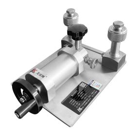
Low-pressure calibration bench |
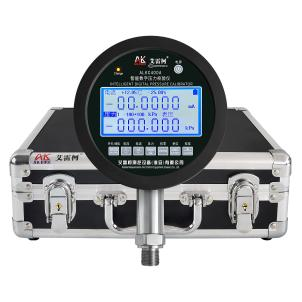
Digital pressure calibrator |
HART handheld communicator |
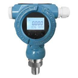
Pressure transmitter |
|
Model |
ALKT511 |
ALKC400A |
ALK475TREX (Chinese Version) |
Various models |
|
Technical Specifications |
Pressurisation method: Manual Pressure: -100 to 100 kPa Medium: Clean air Outlets: 2 Connection: M20×1.5(F) Net weight: 4.6 kg Product dimensions: 320 × 190 × 140 mm
|
Pressure: -100 to 100 kPa Accuracy: ±0.02% FS Temperature compensation: With temperature compensation Current measurement: ±25.0000 mA Voltage measurement: ±50.0000 V DC output: 24 VDC Communication Interface: RS-232/RS-485 Power Supply: Built-in rechargeable battery Connection: M20×1.5 (M) Net Weight: 1 kg Dimensions:156×47×239 mm |
Communication: HART protocol Display: Monochrome screen Language: Chinese DC Output: 24 V DC Power Supply: Built-in rechargeable battery Net Weight: 0.5 kg Dimensions:230 × 130 × 45 mm |
Pressure: -100 to 100 kPa Accuracy: ±0.075% FS ±0.1% FS ±0.2% FS ±0.5% FS Output signal: 4–20 mA + HART Power supply: 24 V DC Connection: M20×1.5 (M)
|
|
Product Dimensions |
|
|
|
|
The entire calibration process must strictly comply with current metrological technical specifications. The primary references include:JJG 882-2019 “Pressure Transmitters,” which applies to the verification, periodic calibration, and in-service inspection of pressure transmitters, and is used to standardize the measurement error, hysteresis, and repeatability of transmitters.
II. Detailed Operational Procedures
(1) Preliminary Preparations
1. Environmental Requirements
Maintain a temperature of (20±2)°C and a relative humidity of ≤85% RH, ensuring there is no condensation. Ensure the site is free of vibration, dust, and corrosive gases.
2. Tool Connection
• Connect the pressure transmitter and the ALKC400A digital pressure calibrator to the ALKT511 outlet using a sealed connection.
• Wiring Method 1 (24V Power Supply for Digital Pressure Calibrator):
(1)Red test lead connection: Insert one end into the standard 24V meter jack, and clip the other end to the transmitter's positive terminal.
(2)Connect a 250-ohm resistor to the negative terminal of the transmitter
(3)Black test lead connection: Insert one end into the standard meter's current terminal, and clip the other end to one side of the 250Ω resistor.
(4)Handheld unit communication cable connection: Plug one end into the handheld unit’s communication port, and attach the alligator clips on the other end to the two terminals of the 250Ω resistor.
(5)Complete the wiring to form a closed circuit
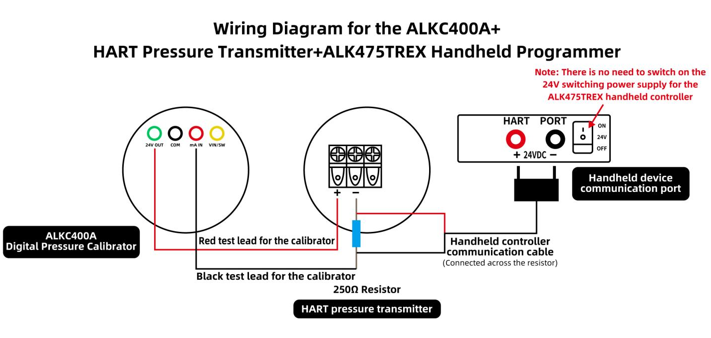
Wiring Diagram (1)
• Wiring Method 2 (24 V power supply for the ALK475TREX handheld unit):
(1)Red test lead connection: Insert one end into the standard meter's current terminal, and clip the other end to the transmitter's negative terminal.
(2)Black test lead connection: Insert one end into the common terminal of the standard meter.
(3)Handheld unit communication cable connection: Plug one end into the handheld unit’s communication port; attach the red clip to the transmitter’s positive terminal, and connect the black clip to the clip on the black test lead.
(4)Complete the wiring to form a closed circuit, then turn on the 24V switching power supply of the ALK475TREX handheld unit.
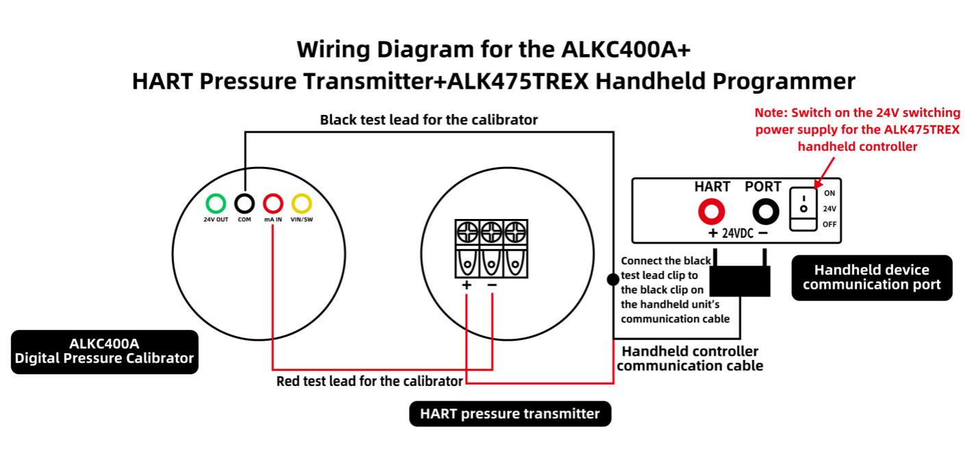
Wiring Diagram (2)
• The transmitter reads 0 at the current atmospheric pressure; a standard manometer measures the transmitter’s current as 12 mA.
(2) The process of positive pressure calibration for HART pressure transmitters
1. Boost calibration process
• First, open the ALKT511 regulating valve, turn the fine-adjustment knob anticlockwise until it stops, and close the relief valve.
• Use the fine-adjustment knob to increase the pressure clockwise to the calibration value of 50 kPa. If the pressure reading from the transmitter deviates from 50 kPa, or if the current reading of 16 mA from the transmitter as measured by the standard gauge deviates, use the handheld calibrator to calibrate the pressure and current values.
• Calibrating the transmitter’s pressure reading:
Select either the low-range fine-tuning or high-range fine-tuning. If the transmitter’s measured pressure is below 50 kPa, select low-range fine-tuning; if it is above 50 kPa, select high-range fine-tuning. Then press the right button, enter the pressure value of 50 kPa, and finally press the right button again to confirm. Both the pressure and current values will be successfully calibrated.
• Follow the same procedure, using the fine-tuning knob to increase the pressure clockwise until it reaches the calibration value of 100 kPa. The current value should be 20 mA. If there is an error, calibrate using the handheld programmer (as described above).
2. Pressure reduction and calibration process
• Use the fine-tuning knob to turn the pressure downwards to 50 kPa. The current reading on the standard gauge should be 16 mA. If there is any deviation, use the handheld calibrator to adjust the pressure and current values.
• Record the relationship between pressure and current at each point, and verify that the hysteresis (the difference in current at the same point during pressure increase and decrease) meets the requirement (≤0.05% FS).
3. Pressure relief process
Open the pressure relief valve and gradually release the pressure in the pipe; once the pressure has been reduced to zero, the measurement is complete.
(3) Calibration procedure for HART pressure transmitters under negative pressure
1. Boost calibration process
• With the ALKT511 pressure-regulating valve in the open position, turn the fine-adjustment knob clockwise until it stops, then close the relief valve.
• Use the fine-adjustment knob to apply pressure in an anti-clockwise direction until the pressure reaches the calibration value of -50 kPa. If there is a deviation between the pressure value measured by the transmitter and -50 kPa, or if there is a deviation in the 8 mA current value measured by the standard gauge, use the handheld calibrator to calibrate the pressure and current values.
• Calibrating the transmitter’s pressure reading:
Select either the low-range or high-range fine-tuning. If the transmitter’s measured pressure is below -50 kPa, select low-range fine-tuning; if it is above -50 kPa, select high-range fine-tuning. Then press the right button, enter the pressure value -50 kPa, and finally press the right button again to confirm. Both the pressure and current values will be successfully calibrated.
• Follow the same procedure, using the fine-tuning function to apply pressure in an anti-clockwise direction. Apply pressure up to the calibration value of -100 kPa; the current value should be 4 mA. If there is an error, calibrate using the handheld programmer (as described above).
2. Pressure reduction and calibration process
• Use the fine-tuning knob to turn clockwise and reduce the pressure to -50 kPa. The current reading on the standard gauge should be 8 mA. If there is a deviation, use the handheld calibrator to adjust the pressure and current values.
• Record the relationship between pressure and current at each point, and verify that the hysteresis (the difference in current at the same point during pressure increase and decrease) meets the requirement (≤0.05% FS).
3. Pressure relief process
Open the pressure relief valve and gradually release the pressure in the pipe; once the pressure has been reduced to zero, the measurement is complete.
III. Important Notes
Proper use
• Operations must be carried out in accordance with standard procedures. When pressurising or depressurising the ALKT511 micro-pressure calibration bench, do so slowly to avoid pressure surges.
• Ensure the connection between the ALKC400A digital pressure calibrator and the handheld controller is correct; take great care to prevent reverse connection.
• Readings at calibration points must be taken only after the standard gauge reading has stabilised, ensuring accurate and real-time recording.
• Upon completion of the test, first slowly depressurise to zero, ensuring there is no residual pressure, then switch off the power supply before removing the instrument under test.
Maintenance and calibration intervals
• Perform metrological verification of the ALKC400A digital pressure calibrator at regular intervals (recommended once a year) to ensure measurement accuracy meets the required standards.
• Switch off the power supply when the pressure gauge is not in use; if it is not used for an extended period, it should be charged once every three months.
• If the micro-pressure stand is not to be used for an extended period, it should be depressurised before storage and covered with a cloth cover to prevent dust from entering the instrument.
IV. Conclusion
This project involved the full-process calibration of HART pressure transmitters for both positive and negative pressures. Utilising the coordinated operation of the ALKT511, ALKC400A and ALK475TREX, the team accurately completed the wiring, zero-point adjustment, span calibration and verification. By manually correcting the deviation between the pressure reading and the 4–20 mA current signal using a HART handheld communicator, instrument performance was optimised to ensure the equipment met performance standards. Adhering to standard operating procedures mitigates risks, enhances measurement stability, and strengthens calibration and maintenance protocols, thereby ensuring the long-term reliable operation of the instruments.
Related News

: Metrological Calibration and Standardisation Procedures for the 0–100 MPa High-Pressure Range")


