

How to Calibrate Pressure Gauges: Standardised Calibration Procedures and Guidelines for Accurate Measurement
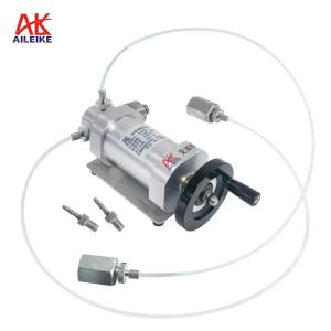
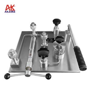
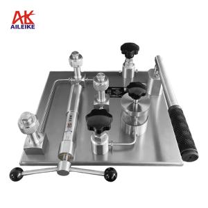
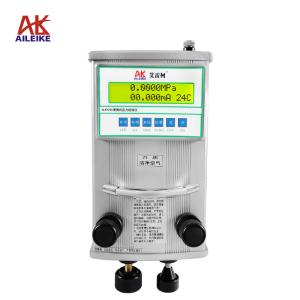
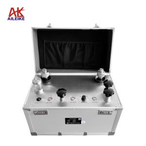
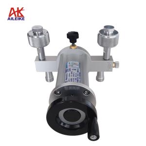
Pressure gauges are core metrological instruments in industry, and their measurement accuracy and stability are of paramount importance. To eliminate deviations and ensure performance, a calibration procedure has been established: the AILEIKE ALKT702 pneumatic calibration bench and ALKC400T precision digital pressure gauge are used to perform full-range calibration of pressure gauges under both positive and negative pressure conditions. Through standardised procedures—including temperature and humidity control, step-wise pressurisation calibration, gentle tapping of the case to prevent drift, and real-time data logging—the measurement range and zero point are precisely calibrated. Throughout the process, emphasis is placed on gradual pressurisation and stable readings to ensure that errors comply with specifications. Based on the principles of equipment compliance, orderly operation and data traceability, these procedures mitigate risks and provide assurance for precise industrial control.
I. Pressure Gauge Calibration Tools
|
Name |
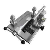
Air Pressure Calibration Bench |
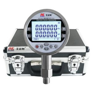
Precision Digital Pressure Gauge |
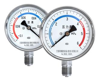
Stainless steel pressure gauge |
|
Model |
ALKT702 |
ALKC400T |
Y-100BF |
|
Technical Specifications |
Pressurisation method: Manual Pressure range: -0.095 to 6 MPa Medium: Clean air Outlets: 2 Connection: M20×1.5 (F) Net weight: 10 kg Product dimensions: 400 × 320 × 185 mm |
Pressure: -0.1 to 6 MPa Accuracy: 0.05% FS Current measurement: ±30.0000 mA Voltage measurement: ±30.0000 V DC output: 24 VDC Communication interfaces: RS-232/RS-485 Temperature compensation: With temperature compensation Power supply: Built-in rechargeable battery Net weight: 0.6 kg Connection: M20×1.5 (M) Dimensions: 110×50×185 mm
|
Pressure: -0.1 to 0 MPa / 0 to 6 MPa Accuracy: Class 1.6 Material: Stainless steel Dial diameter: φ100 mm Connection: M20×1.5 (M) Net weight: 0.35 kg Product dimensions: 100 × 42 × 140 mm |
|
Product Dimensions |
|
|
|
The entire verification process must be carried out in strict accordance with current metrological technical specifications. The main references include:JJG52-2013 ‘General Pressure Gauges, Pressure-Vacuum Gauges and Vacuum Gauges with Elastic Elements’, which applies to the initial verification, periodic verification and in-service inspections of general pressure gauges, pressure-vacuum gauges and vacuum gauges with elastic elements, and covers on-site indicating pressure measuring instruments commonly used in industry.
II. Detailed Explanation of the Operational Process
(1) Preliminary Preparations
1. Environmental Requirements
The temperature must be maintained at (20±2) °C, with relative humidity ≤85% RH and no condensation. Ensure that the site is free from vibration, dust and corrosive gases.
2. Connection of Equipment
• Connect the standard gauge ALKC400T and the pressure gauge under test (Y-100BF) to the outlet of the ALKT702, ensuring a sealed connection.
(2) The process of calibrating a pressure gauge against atmospheric pressure
1. Pressurisation procedure
• First, open the pressure-regulating valve on the ALKT702, then push the positive/negative pressure selector valve inwards (do not switch under pressure), then turn the fine-adjustment knob anti-clockwise until it stops, and close the relief valve.
• Use the lever to apply pressure, stopping at approximately the calibration point; then use the fine-adjustment knob to slowly turn clockwise until the pressure reaches the calibration point of 1 MPa. Once the pressure has stabilised and the standard reading no longer fluctuates, check the pressure reading on the pressure gauge under test. Then, gently tap the side of the pressure gauge’s casing with your finger (do not tap the glass or tap forcefully), observe the position of the pointer, and record the reading once it has stabilised after tapping. Use the reading after tapping as the actual calibration reading for that pressure point, and calculate the error.
• Next, use the hand-operated pressure rod to pressurise to approximately 1.9 MPa and 2.9 MPa, then stop. Use the fine-adjustment knob to slowly turn clockwise to the calibration points of 2 MPa and 3 MPa. Once the pressure has stabilised, tap the pressure gauge under test and record the value.
• Before adjusting to the next calibration point, first close the shut-off valve, then use the fine-adjustment knob to slowly turn clockwise to the 4 MPa calibration point. Once the pressure has stabilised, tap the pressure gauge under test and record the reading.
• Finally, use the fine-adjustment knob to slowly turn clockwise directly to the 5 MPa and 6 MPa calibration points. Once the pressure has stabilised, tap the pressure gauge under test and record the readings.
2. Pressure Reduction Procedure
• First, slowly open the relief valve and reduce the pressure until it reaches the test point, then stop. Close the relief valve and use the fine-adjustment valve to slowly turn the pressure counter-clockwise to 5 MPa at the test point. Once the pressure has stabilised, tap the pressure gauge under test and record the reading.
• Repeat the same procedure to set the pressure to the test points of 4 MPa, 3 MPa, 2 MPa and 1 MPa. Observe the pressure reading on the pressure gauge under test, tap the gauge, and record the reading once it has stabilised after tapping.
3. Pressure Relief Procedure
Open the pressure relief valve and the shut-off valve in sequence to gradually release the pressure within the pipeline. Once the pressure has been relieved to 0, the test is complete.
(3) The vacuum calibration process for pressure gauges
1. Pressure-building procedure
• First, remove the pressure gauge under test for measuring positive pressure and fit the one for measuring negative pressure. Pull the positive/negative pressure changeover valve outwards (do not switch valves whilst under pressure). Next, open the pressure-regulating valve, then turn the ALKT702 fine-adjustment knob clockwise until it stops. Close the pressure-relief valve.
• Use the hand pump to create a vacuum, stopping when the pressure reaches approximately the calibration value. Slowly turn the fine-adjustment knob anti-clockwise to the calibration point of –0.02 MPa. Once the pressure has stabilised, tap the pressure gauge under test and record the reading.
• Repeat the same procedure to adjust to the calibration points of –0.04 MPa, –0.06 MPa, –0.08 MPa and –0.095 MPa. Observe the pressure reading on the pressure gauge under test, tap the gauge, and record the reading once it has stabilised after the tap.
2. Pressure Reduction Process
• First, slowly open the relief valve to reduce the pressure to approximately the calibration value, then stop. Close the relief valve and use the fine-adjustment valve to slowly turn clockwise to the calibration point of –0.08 MPa. Once the pressure has stabilised, tap the pressure gauge under test and record the reading.
• Repeat the same procedure to adjust to the calibration points of –0.06 MPa, –0.04 MPa and –0.02 MPa. Observe the pressure reading on the pressure gauge under test, tap the gauge, and record the reading once it has stabilised.
3. Depressurisation procedure
Open the relief valve and gradually release the pressure in the pipeline until it reaches 0; the measurement is then complete.
III. Points to Note
Proper Use
• When performing calibration, ensure that the permissible error of the reference gauge is less than that of the gauge under test, to ensure that the calibration results are accurate and reliable, and comply with metrological standards.
• Operations must follow standard procedures; when pressurising or depressurising the ALKT702 pressure calibration stand, do so gradually to avoid pressure surges.
• Pressurise to the calibration point and record the reading once the reference gauge has stabilised; for the pressure gauge under test, once the pressure has stabilised, tap the case gently and take the reading immediately after the tap to ensure accuracy.
• Upon completion of the test, first slowly depressurise to zero and ensure there is no residual pressure before removing the instrument under test.
Maintenance and Calibration Intervals
• The ALKC400T precision digital pressure gauge should undergo periodic metrological verification (recommended once a year) to ensure measurement accuracy meets standards.
• When the pressure gauge is not in use, the power should be switched off; if not used for an extended period, it should be recharged once every three months.
• If the pneumatic calibration stand is not to be used for an extended period, it should be depressurised before storage and covered with a cloth cover to prevent dust from entering the instrument.
IV. Conclusion
The calibration, testing and measurement of the pressure gauges have been successfully completed. Throughout the process, we strictly adhered to the standardised procedure involving stepwise pressure increases and decreases, pressure stabilisation and readings, and point-by-point re-measurement. We eliminated indication drift by gently tapping the gauge casing, accurately recorded and verified the data at each test point, and comprehensively verified the measurement accuracy and operational stability of the pressure gauges. The entire testing process was conducted in accordance with rigorous standards, with authentic data, effectively identifying any measurement deviations in the instruments and ensuring that all indicators comply with metrological standards.