


Recommended Pressure Standards - ALKB202
Analysis of the Recommended Standard Operating Procedures for the Installation of AILEIKE Pressure Sensor Calibration and Verification Equipment
In the fields of industrial automation and pressure calibration, pressure transducers serve as critical sensing components; their measurement accuracy directly impacts equipment operational stability and data accuracy. Therefore, it is essential to perform regular, standardized calibration of these devices. This paper describes the calibration of the ALKPTS503 pressure sensor using the ALKB202 portable micro-pressure pump and the ALKC400T precision digital pressure gauge. The calibration process comprises three core stages: preliminary preparation, positive pressure calibration, and negative pressure calibration. Through proper tool connections, precise pressure adjustment, and meticulous data recording, the sensor’s performance is tested and measurement traceability is established, ensuring the reliability of the pressure sensor’s measurement data.
Pressure Sensor Calibration Tool
|
Name |
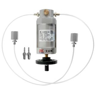
Compact Low-Pressure Pump |
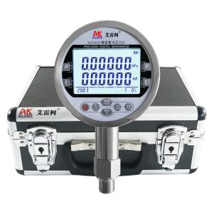
Precision Digital Pressure Gauge |
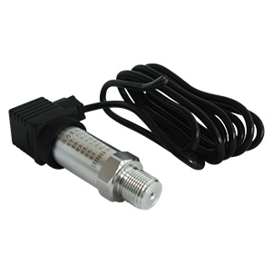
Pressure Sensor |
|
Model |
ALKB202 |
ALKC400T |
ALKPTS503 |
|
Technical Specifications |
Pressure Application Method: Manual Pressure Range: -90 to 600 kPa Medium: Clean air Outlets: 2 Connection: M20×1.5 female Hose: 680 mm Guide Hose: 300 mm Guide Fitting: M10×1 to φ6 Net Weight: 1.8 kg Product Dimensions: 220×90×80 mm
|
Pressure: -100 to 600 kPa Accuracy: 0.05% FS Temperature Compensation: With temperature compensation Current Measurement: ±30.0000 mA Voltage Measurement: ±30.0000 V DC Output: 24 VDC Communication Interface: RS-232/RS-485 Power Supply: Built-in rechargeable battery Net Weight: 0.6 kg Connection: M20×1.5 male Dimensions: 110×50×185 mm |
Pressure: -90 to 600 kPa Lead length: 2 meters Accuracy: 0.5% FS Output signal: 4 to 20 mA Power supply: 24 VDC
|
|
Product Dimensions |
|
|
|
The entire verification process must strictly comply with current metrological technical specifications. The primary references include: JJG 860-2015 “Pressure Transducers (Static),” which applies to the initial verification, periodic verification, and in-service inspection of static pressure transducers. A device or apparatus capable of sensing pressure signals and converting them into usable electrical output signals according to a specific relationship.
Detailed Operating Procedures
Preliminary Preparations
1. Environmental Requirements
Maintain a temperature of (20±2)°C, relative humidity ≤85% RH, and ensure there is no condensation. Ensure the site is free of vibration, dust, and corrosive gases.
2. Connecting Tools
• Securely connect the ALKPTS503 pressure sensor and the ALKC400T precision digital pressure gauge to the ALKB202 output port.
• Wiring Instructions:
(1) Connect the red test lead of the ALKC400T to the 24V output port of the standard meter, and the black test lead to the current input port.
(2) Clip the red alligator clip on the other end to the sensor’s red wire (positive terminal) and the black alligator clip to the sensor’s blue wire (negative terminal). The ALKC400T digital pressure gauge is now successfully connected to the pressure sensor. At the current atmospheric pressure, when the sensor’s pressure reading is 0 MPa, the digital pressure gauge should measure a current value of 6 mA from the sensor.
Positive Pressure Calibration Procedure for Pressure Sensors
1. Pressure Increase Procedure
• First, turn the ALKB202 fine-adjustment valve counterclockwise until it stops. Then close the relief valve. Next, use the fine-adjustment valve to increase the pressure clockwise to the calibration value of 150 kPa. The standard gauge measures a current value of 9.5 mA for the pressure sensor.
• Next, use the fine-tuning valve to increase the pressure clockwise to the calibration value of 300 kPa; the current reading is 13 mA.
• Repeat the same procedure, using the fine-tuning valve directly to increase pressure to the calibration values of 450 kPa and 600 kPa; the corresponding current values are 16.5 mA and 20 mA, respectively.
2. Depressurization Process
• Use the fine-tuning valve to reduce pressure counterclockwise to 450 kPa; the standard gauge measures a current value of 16.5 mA for the pressure sensor.
• Using the same procedure, directly reduce the pressure using the fine-adjustment valve to the calibration points of 300 kPa and 150 kPa; the corresponding current values are 13 mA and 9.5 mA, respectively.
3. Pressure Relief Process
Open the relief valve to gradually release the pressure in the pipeline. When the pressure reaches 0, the measurement is complete.
Vacuum Calibration Procedure for Pressure Sensors
1. Pressurization Process
• First, turn the ALKB202 fine-adjustment valve clockwise until it stops. Then close the relief valve. Next, use the fine-adjustment valve to pressurize the system counterclockwise to the calibration value of -25 kPa. The standard gauge measures a current value of 5.4 mA for the pressure sensor.
• Next, use the fine-tuning valve to increase the pressure counterclockwise to the calibration value of -50 kPa; the current reading is 4.8 mA.
• Repeat the same procedure, using the fine-tuning valve to pressurize directly to the calibration values of -75 kPa and -90 kPa; the corresponding current values are 4.3 mA and 4.0 mA, respectively.
2. Depressurization Process
• Use the fine-tuning valve to depressurize clockwise until the pressure reaches -75 kPa; the standard gauge measures a current value of 4.3 mA for the pressure sensor.
• Using the same procedure, depressurize to the calibration points of -50 kPa and -25 kPa; the corresponding current values are 4.8 mA and 5.4 mA, respectively.
3. Depressurization Process
Open the relief valve to gradually release the pressure in the pipeline. When the pressure reaches 0, the measurement is complete.
Precautions
Proper Use
• Follow standard operating procedures. When pressurizing or depressurizing the ALKB202 lightweight micro-pressure pump, do so slowly to avoid pressure surges.
• Ensure the wiring of the ALKC400T precision digital pressure gauge is correct; take care to prevent reversed connections.
• Read the calibration point only after the standard gauge reading has stabilized, and record the reading accurately and in real time.
• Upon completion of the test, slowly depressurize the system to zero and ensure there is no residual pressure before removing the instrument under test.
Maintenance and Calibration Schedule
• Perform periodic metrological verification on the ALKC400T precision digital pressure gauge (recommended once a year) to ensure measurement accuracy meets standards.
• When the pressure gauge is not in use, turn off the power. If not used for an extended period, recharge it once every three months.
• If the micro-pressure pump is not used for an extended period, depressurize it before storage and cover it with a cloth cover to prevent dust from entering the instrument.
Conclusion
In summary, the calibration of the ALKPTS503 pressure sensor strictly adhered to calibration specifications. Through preliminary preparations, step-by-step positive and negative pressure calibration, and proper operation, the sensor inspection was successfully completed, effectively verifying the reliability of its measurement accuracy. Standardized operation and regular maintenance are key to ensuring the long-term stable operation of pressure sensors. Calibrating the calibration tools according to schedule provides a solid foundation for stable equipment operation and reliable data recording.
Related News


