

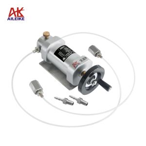
AILEIKE Operational Guidelines for the Calibration of Stainless Steel Pressure Gauges: Positive and Negative Pressure, Full Range
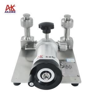
Pressure gauges are critical pressure monitoring and measurement instruments in industrial production; their measurement accuracy determines process stability and equipment operation. Consequently, standardised calibration, inspection and measurement operations must be carried out regularly. For this operation, the ALKT511 low-pressure calibration bench and the ALKC400T precision digital pressure gauge were utilised to perform fixed-point calibration and verification of stainless steel pressure gauges, with the calibration work conducted in a compliant environment. The calibration covered all full-range calibration points for both positive and negative pressure, strictly adhering to the standard procedures for pressurisation, stabilisation, depressurisation and venting. By gently tapping the case to standardise readings and accurately calculating errors, we strictly observed metrological operating procedures, effectively identifying deviations in instrument readings and ensuring the accuracy and reliability of the pressure gauge measurement data.
I. Pressure Gauge Calibration Tools
|
Name |
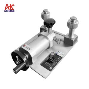
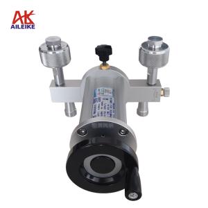
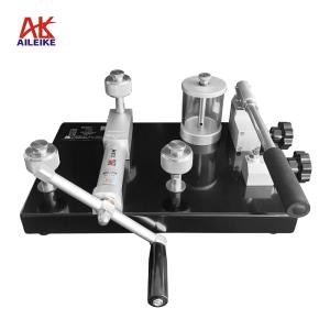
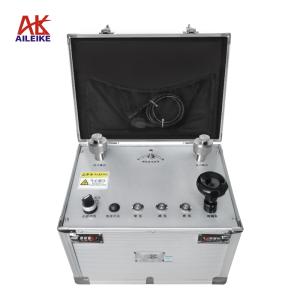
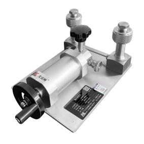
Low-pressure calibration bench |
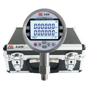
Precision Digital Pressure Gauge |
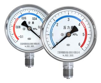
Stainless steel pressure gauge |
|
Model |
ALKT511 |
ALKC400T |
Y-100BF |
|
Technical Specifications |
Pressurisation method: Manual Pressure: -100 to 600 kPa Medium: Clean air Outlets: 2 Connection: M20×1.5 (F) Net weight: 4.6 kg Product dimensions: 320 × 190 × 140 mm
|
Pressure: -100 to 600 kPa Accuracy: 0.05% FS Current measurement: ±30.0000 mA Voltage measurement: ±30.0000 V DC output: 24 V DC Communication interface: RS-232/RS-485 Temperature compensation: With temperature compensation Power supply: Built-in rechargeable battery Net weight: 0.6 kg Connection: M20×1.5 (M) Dimensions: 110×50×185 mm
|
Pressure: -100 to 0 kPa / 0 to 600 kPa Accuracy: Class 1.6 Material: Stainless steel Dial diameter: φ100 mm Connection: M20×1.5 (M) Net weight: 0.35 kg Product dimensions: 100 × 42 × 140 mm
|
|
Product Dimensions |
|
|
|
The entire verification process must be carried out in strict accordance with current metrological technical specifications. The main references include:JJG52-2013 ‘General Pressure Gauges, Pressure-Vacuum Gauges and Vacuum Gauges with Elastic Elements’, which applies to the initial verification, periodic verification and in-service inspections of general pressure gauges, pressure-vacuum gauges and vacuum gauges with elastic elements, and covers on-site indicating pressure measuring instruments commonly used in industry.
II. Detailed Explanation of Operational Procedures
(1) Preliminary Preparations
1. Environmental Requirements
The temperature must be maintained at (20±2) °C, with relative humidity ≤85% RH and no condensation. Ensure that the site is free from vibration, dust and corrosive gases.
2. Connection of Equipment
Connect the standard gauge ALKC400T and the pressure gauge under test (Y-100BF) to the outlet of the ALKT511 via a sealed connection.
(2) The process of calibrating a pressure gauge against atmospheric pressure
1. Pressure-building procedure
• First open the regulating valve on the ALKT511, then turn the fine-adjustment knob anti-clockwise until it stops, and close the relief valve.
• Use the fine-adjustment knob to apply pressure by turning it clockwise until the calibration value of 150 kPa is reached. Once the pressure has stabilised and the standard reading no longer fluctuates, note the pressure reading on the pressure gauge under test. Then, gently tap the side of the pressure gauge’s casing with your finger (under no circumstances should you tap the glass or strike it forcefully), observe the position of the pointer, and record the reading once it has stabilised after the tap. Use the reading after tapping as the actual calibration reading for that pressure point, and calculate the error.
• Repeat the same procedure, using the fine-adjustment knob to increase the pressure clockwise to the calibration points of 300 kPa, 450 kPa and 600 kPa. Check the pressure reading on the pressure gauge under test, tap the gauge, and record the reading once it has stabilised after tapping.
2. Pressure reduction procedure
• Use the fine-adjustment knob to slowly adjust the pressure to the test points of 450 kPa; once the pressure has stabilised, tap the pressure gauge under test and record the reading.
• Repeat the same procedure to adjust the pressure to the test points of 300 kPa and 150 kPa; check the pressure reading on the pressure gauge under test, tap the gauge, and record the reading once it has stabilised.
3. Pressure Relief Procedure
Open the pressure relief valve and gradually release the pressure in the pipework; once the pressure has been reduced to zero, the measurement is complete.
(3) The vacuum calibration process for pressure gauges
1. Pressurisation Procedure
• First, remove the pressure gauge under test for positive pressure and fit the one for negative pressure. Turn the fine-adjustment knob clockwise until it stops, then close the pressure relief valve.
• Turn the fine-adjustment knob anti-clockwise to apply pressure, increasing it to the calibration value of –25 kPa. Once the pressure has stabilised, tap the pressure gauge under test and record the reading.
• Repeat the same procedure for the calibration points of −50 kPa, −75 kPa and −100 kPa. Observe the pressure reading on the pressure gauge under test, tap the gauge, and record the reading once it has stabilised after tapping.
Note:
• If the fine-adjustment knob cannot be turned whilst evacuating and the calibration value has not been reached, a second pressurisation is required.
• Procedure for re-pressurisation: First close the pressure-regulating valve, then open the relief valve; next, turn the fine-adjustment knob clockwise until it can no longer be turned; close the relief valve; then open the pressure-regulating valve; finally, use the fine-adjustment knob to turn it anti-clockwise to the calibration point.
2. Depressurisation process
• First, slowly open the relief valve to reduce the pressure to approximately the calibration value; close the relief valve; then use the fine-adjustment valve to slowly adjust the pressure to the calibration point minus 75 kPa. Once the pressure has stabilised, tap the pressure gauge under test and record the reading.
• Repeat the same procedure to adjust to the calibration points of –50 kPa and –25 kPa. Check the pressure reading on the pressure gauge under test, tap the gauge, and record the reading once it has stabilised after tapping.
3. Pressure Relief Procedure
Open the pressure relief valve and gradually release the pressure in the pipeline until it reaches 0; the measurement is then complete.
III. Precautions
Proper Use
• During calibration, ensure that the permissible error of the standard gauge is less than that of the gauge under test, to ensure that the calibration results are accurate and reliable, and comply with metrological standards.
• Operations must follow standard procedures; when pressurising or depressurising the ALKT511 low-pressure calibration stand, do so slowly to avoid pressure surges.
• Pressurise to the calibration point and record the reading once the reference gauge’s value has stabilised; for the pressure gauge under test, once the pressure has stabilised, tap the case lightly and take the reading immediately after the tap to ensure accuracy.
• Upon completion of the test, first slowly depressurise to zero and ensure there is no residual pressure before removing the instrument under test.
Maintenance and Calibration Intervals
• The ALKC400T precision digital pressure gauge should undergo periodic metrological verification (recommended once a year) to ensure measurement accuracy meets standards.
• When the pressure gauge is not in use, the power should be switched off; if not used for an extended period, it should be recharged once every three months.
• If the low-pressure calibration stand is not to be used for an extended period, it should be depressurised before storage and covered with a cloth cover to prevent dust from entering the instrument.
IV. Conclusion
This pressure gauge calibration, testing and measurement programme, utilising Aileko calibration equipment, was carried out in strict accordance with standardised procedures to complete full-range testing for both positive and negative pressures. Through meticulous operations such as standardised pressure regulation, tapping the case to take readings, and secondary pressurisation under vacuum, measurement deviations were effectively minimised. This enabled a precise verification of the pressure gauges’ metrological errors and overall performance, ensuring that data at each test point was accurate and reliable, and in compliance with metrological standards. The routine conduct of pressure gauge calibration and testing enables the timely correction of measurement deviations to prevent data inaccuracies. At the same time, the standardised implementation of periodic verification and daily maintenance of calibration equipment ensures the sustained accuracy of measurement and calibration, providing stable and reliable technical support for the operation of industrial equipment, the control of production processes, and the compliance of metrological data.
Related News