

A Comprehensive Analysis of the Entire Process for Verifying the Opening and Closing of Pressure Switch Contacts
Pressure switches are core measurement and control components in industrial hydraulic systems, automatically opening and closing circuits in response to changes in pressure. Deviations in pressure switch parameters can easily lead to inaccurate calibration readings; therefore, it is essential to carry out regular pressure measurements, performance tests and set-point calibration. This calibration was carried out under standard environmental conditions of (20±2) °C and relative humidity ≤ 85% RH, using an ALKT803 hydraulic calibration bench and an ALKC400A digital pressure calibrator to test the operational status of the pressure switch’s normally open and normally closed contacts respectively. By applying and releasing pressure gradually to test the contact make-and-break behaviour, operational risks such as pressure surges and wiring errors were avoided, ensuring the authenticity and accuracy of the test data.
I. Tools for Calibrating Pressure Switches
|
Name |
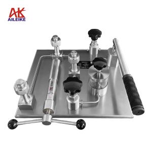
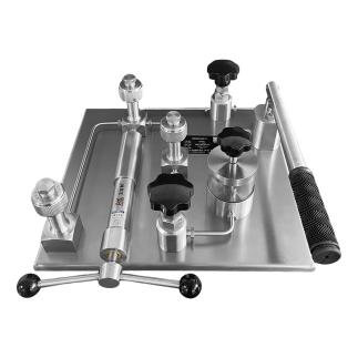
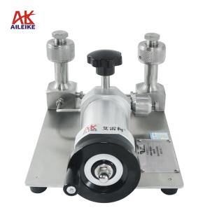
Hydraulic calibration bench |
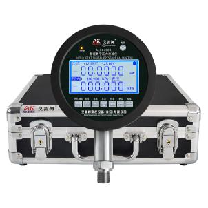
Digital Pressure Calibrator |
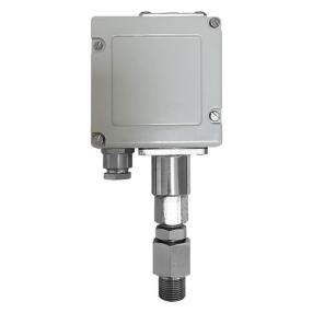
Pressure switch |
|
Model |
ALKT803 |
ALKC400A |
Various models |
|
Technical Specifications |
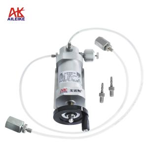
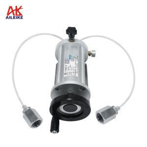
Pressurisation method: Manual Pressure range: 0–60 MPa Medium: Purified water or calibration oil Outlets: 3 Connection: M20×1.5 (F) Net weight: 14 kg Product dimensions: 410×410×180 mm
|
Pressure: 0–60 MPa Accuracy: 0.02% FS Temperature compensation: With temperature compensation Current measurement: ±25.0000 mA Voltage measurement: ±50.0000 V DC output: 24 V DC Communication interface: RS-232/RS-485 Power supply: Built-in rechargeable battery Connection: M20×1.5 (M) Net weight: 1 kg Dimensions: 156 × 47 × 239 mm
|
Pressure switch: 0–60 MPa Set point: 30 MPa Contact type: Normally open/normally closed switch Wetted parts material: Stainless steel Mounting thread: M20×1.5 (default)
|
|
Product Dimensions |
|
|
|
The entire verification process must be carried out in strict accordance with current metrological technical specifications. The main references include:JJG 544-2011 ‘Pressure Controllers’, which applies to the initial verification, subsequent verification and in-service inspection of pressure, vacuum and pressure-vacuum controllers (including mechanical and electronic types); these are pressure control devices that operate without an external power supply and rely on pressure changes to directly drive mechanical components to close or open contacts.
II. Detailed Explanation of the Operational Process
(1) Preliminary Preparations
1. Environmental Requirements
The temperature must be maintained at (20±2) °C, with relative humidity ≤85% RH and no condensation. Ensure that the site is free from vibration, dust and corrosive gases.
2. Filling, Pressurising and Press-through of the Hydraulic Test Bench
• Prepare the pressure-transmitting medium (purified water or calibration oil).
• First, unscrew the pressure relief valve on the ALKT803 hydraulic calibration bench and fill the reservoir with the medium, ensuring it is sufficiently filled (to at least two-thirds capacity). Once filling is complete, reattach and tighten the pressure relief valve.
• Next, purge any excess air from the hydraulic bench. First, unscrew the plugs from the three outlet ports, open the pressure-regulating valve, relief valve and overpressure shut-off valve, turn the fine-adjustment valve anti-clockwise to the appropriate position, and close the relief valve. Then, use the lever to pressurise the system, directing the pressure to the three outlet ports.
3. Connecting the equipment
• Connect the pressure switch and the ALKC400A digital pressure calibrator to the outlet of the ALKT803 hydraulic calibration bench using sealed connections. Press the Switch/Peak button on the ALKC400A to switch to pressure switch measurement mode.
• Pressure switch pre-adjustment: Open the protective cover of the adjustment knob on top of the pressure switch, have the adjustment tool ready, and allow sufficient travel for clockwise (increase) and anti-clockwise (decrease) rotation to set the pressure switch setpoint.
• Wiring instructions:
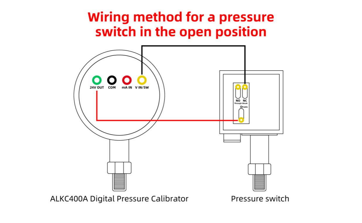
(1) Connect the red test lead of the ALKC400A to the 24V output terminal of the standard gauge, and the black test lead to the pressure switch measurement terminal.
(2) Clip the other end of the red alligator clip to the common terminal (COM) of the pressure switch, and the black alligator clip to the normally open (NC) or normally closed (NO) terminal.
(3) Now, first clip the black crocodile clip to the normally open (NC) terminal. At this point, the ALKC400A pressure switch display will show the word ‘Open’, confirming that the pressure switch’s normally open (open circuit) state is functioning correctly and that the wiring is correct.
(2) Procedure
Key calibration steps: Set the target pressure to 30 MPa. Rotate the pressure switch adjustment knob slightly (clockwise to increase pressure, anti-clockwise to decrease pressure), and carry out pressure testing using the calibration bench to precisely calibrate the pressure switch’s actuation point to the target pressure of 30 MPa. Once calibration is complete, keep the knob in its set position.
1. Testing the closing and opening of the pressure switch whilst in the normally open state
• Apply pressure using the ALKT803 lever; stop when the pressure reaches approximately 5–10 MPa. Close the pressure-regulating valve and the overpressure shut-off valve, then use the fine-adjustment knob to turn clockwise until the upper cut-off value (actuation pressure) for closing the switch reaches 30 MPa. You will hear a ‘beep’ from the instrument’s buzzer, the contact status will change, and the switch test on the standard gauge interface will change from ‘open’ to ‘closed’. the pressure switch switches from the open state to the closed state; record the actuation pressure value.
• Continue to reduce the pressure by turning the fine-adjustment knob anti-clockwise until the lower cut-off value (reset value) of 27 MPa is reached; again, a “beep” from the instrument will sound, the contact status will change, and the switch test on the standard gauge interface will change from “closed” to “open”; the pressure switch switches from the closed state to the open state; record the reset pressure value.
• Once the test is complete, open the pressure relief valve, pressure-regulating valve and overpressure shut-off valve in sequence to reduce the pressure to 0; the measurement is then complete.
2. Testing the closing and opening of a pressure switch in the normally closed state
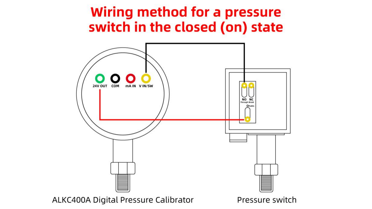
• First, clip the black alligator clip onto the normally open (NO) terminal; you will then see that the pressure switch is in the normally closed state, and the ALKC400A pressure switch test display will show the word ‘Open’.
• Open the pressure-regulating valve, the relief valve and the overpressure shut-off valve; turn the fine-adjustment valve anti-clockwise to the appropriate position, then close the relief valve.
• Apply pressure using the lever, stopping at approximately 5–10 MPa. Close the pressure-regulating valve and the overpressure shut-off valve, then use the fine-adjustment valve to turn clockwise to the upper cut-off value (actuation value) of 30 MPa at which the switch opens. You will hear a ‘beep’ from the instrument’s buzzer, the contact status will change, and the switch test on the standard gauge interface will change from ‘Open’ to ‘Closed’. the pressure switch switches from the closed state to the open state; record the actuation pressure value.
• Continue to reduce the pressure by turning the fine-adjustment valve anti-clockwise until it reaches the lower cut-off value (reset value) of 27 MPa; again, you will hear a ‘beep’ from the instrument, the contact status will change, the ‘Open/Closed’ indicator on the standard gauge will change from ‘Open’ to ‘Closed’, and the pressure switch will switch from the open state to the closed state; record the reset pressure value.
• Once the test is complete, open the pressure relief valve, pressure-regulating valve and overpressure shut-off valve in sequence to reduce the pressure to 0; the measurement is then complete.
III. Points to Note
Proper Use
• Operations must be carried out in accordance with standard procedures. Pressure must be increased and decreased gradually on the ALKT803 hydraulic calibration stand to avoid pressure surges.
• The wiring of the ALKC400A digital pressure calibrator must be clearly identified; take great care to prevent reverse connections.
• Readings at calibration points must be taken only after the value on the standard gauge has stabilised, ensuring accurate and real-time recording.
• Upon completion of the test, first slowly depressurise the system to zero; the instrument under test may only be removed once all residual pressure has been released.
Maintenance and Calibration Intervals
• The ALKC400A digital pressure calibrator must undergo periodic metrological verification (recommended once a year) to ensure measurement accuracy meets standards.
• Switch off the power supply when the pressure gauge is not in use; if not used for an extended period, recharge the battery once every three months.
• If the hydraulic test bench is not to be used for an extended period, depressurise it before storage, empty the fluid from the reservoir cup and cover it with a cloth cover to prevent dust from entering the instrument.
IV. Conclusion
Pressure measurement, contact testing and set-point calibration of pressure switches are key to ensuring the reliable operation of hydraulic systems. In this instance, based on on-site operating conditions, we conducted item-by-item testing of both normally open and normally closed switch configurations, precisely measuring the critical pressures for activation and deactivation, verifying actuation and reset response performance, and identifying potential hazards such as contact failure and set-point drift. Standardised calibration effectively corrects parameter deviations, ensuring the switches operate reliably at the set pressure. A system of periodic testing should be established for routine calibration and measurement. Pressure switches should be retested and calibrated at regular intervals to promptly eliminate performance deviations, minimise the risk of overpressure failures, and effectively ensure the long-term, stable operation of the entire hydraulic system.