


Recommended Pressure Standards - ALKB201
AILEIKE Differential Pressure Transmitter Metrological Verification and Calibration Procedure: Recommended Pressure Standards
To ensure the metrological accuracy and operational stability of differential pressure transmitters, guarantee the precision and reliability of their output signals, and meet the metrological control requirements for pressure parameters during production, this differential pressure transmitter calibration work is being conducted. During the calibration process, the ALKB201 micro-pressure pump and the ALKC400T precision digital pressure gauge (differential pressure type) were used as core calibration tools. In an environment where temperature and humidity met metrological calibration requirements, stepwise positive and negative pressure tests were conducted to precisely record the current values at each test point, ensuring that all performance indicators conform to metrological standards.
Differential Pressure Transmitter Calibration Tool
|
Name |
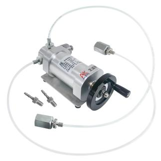
Low-Pressure Pump |
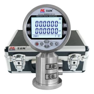
Precision Digital Pressure Gauge |
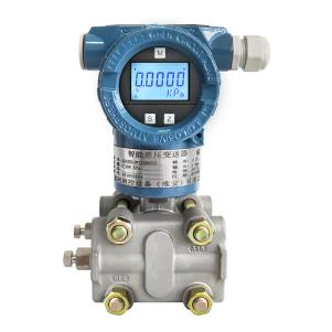
Digital Differential Pressure Transmitter |
|
Model |
ALKB201 |
ALKC400T (Differential Pressure Type) |
ALK3051DP |
|
Technical Specifications |
Pressure Application Method: Manual Pressure Range: -6000 to 6000 Pa Medium: Clean air Outlets: 2 Connection: M20×1.5 female Hose: 680 mm Guide Hose: 300 mm Guide Fitting: M10×1 to φ6 Net Weight: 1.8 kg Product Dimensions: 220×120×90 mm |
Pressure: -6000 to 6000 Pa Accuracy: 0.05% FS Temperature Compensation: With temperature compensation Current Measurement: ±30.0000 mA Voltage Measurement: ±30.0000 V DC Output: 24 VDC Communication Interface: RS-232/RS-485 Power Supply: Built-in rechargeable battery Connection: M10×1 Net Weight: 0.85 kg Dimensions: 110×75×190 mm |
Pressure: -6000 to 6000 Pa Accuracy: 0.2% FS Output Signal: 4–20 mA Power Supply: 24 VDC Net Weight: 3.5 kg |
|
Product Dimensions |
|
|
|
The entire calibration process must strictly comply with current metrological technical specifications. The primary reference is JJG 882-2019 “Pressure Transmitters,” which applies to the verification, periodic calibration, and in-service inspection of pressure transmitters, and is used to standardize the measurement error, hysteresis, and repeatability of transmitters.
Detailed Operational Procedures
Preliminary Preparations
1. Environmental Requirements
Temperature must be maintained at (20±2)°C, relative humidity ≤85% RH, with no condensation. Ensure the site is free of vibration, dust, and corrosive gases.
2. Instrument Connections
• Connect the differential pressure transmitter ALK3051DP and the Precision digital pressure gauge alkc400T (differential pressure type, hereinafter referred to as the differential pressure gauge) to the outlet of the ALKB201 micro-pressure pump with a sealed connection.
(1) Connect the high-pressure port of the differential pressure gauge to one of the output ports of the ALKB201.
(2) Connect the high-pressure port of the differential pressure transmitter to the other output port of the ALKB201.
• Wiring Instructions:
(1) Connect the red test lead of the differential pressure gauge to the 24V output terminal, and the black test lead to the current terminal.
(2) Clip the other end’s red alligator clip to the transmitter’s positive terminal and the black alligator clip to the transmitter’s negative terminal. The differential pressure gauge successfully powers the transmitter. At the same time, when the transmitter’s pressure reading is 0 under current atmospheric pressure, the differential pressure gauge measures a current value of 12 mA from the transmitter.
Positive Pressure Calibration Process for the Differential Pressure Transmitter
1. Pressure Increase Process
• First, turn the ALKB201 handle counterclockwise until it stops. Then, turn the fine adjustment knob counterclockwise to a suitable position. Close the pressure relief valve, and then use the handle to slowly increase the pressure clockwise. Stop when the pressure reaches approximately the calibration value. Next, use the fine adjustment knob to turn clockwise until the pressure reaches the calibration value of 1500 Pa. The differential pressure gauge measures a current value of 14 mA from the differential pressure transmitter.
• Next, use the handle to slowly increase the pressure clockwise until it reaches approximately the calibration value, then stop. Use the fine adjustment knob to set the pressure to 3000 Pa, at which point the current reading is 16 mA.
• Repeat the same procedure, pressurizing to calibration values of 4500 Pa and 6000 Pa; the corresponding current values are 18 mA and 20 mA, respectively.
2. Depressurization Process
• First, use the handle to slowly depressurize counterclockwise until the pressure is approximately at the calibration value, then stop. Use the fine-tuning knob to adjust to the calibration value of 4500 Pa; the differential pressure gauge measures a current value of 18 mA for the differential pressure transmitter.
• Repeat the same procedure, reducing pressure to the calibration points of 3000 Pa and 1500 Pa; the corresponding current values are 16 mA and 14 mA, respectively.
3. Pressure Relief Process
Open the relief valve to gradually release the pressure in the pipeline. When the pressure reaches 0, the measurement is complete.
Negative Pressure Calibration Process for Differential Pressure Transmitter
1. Pressurization Process
• First, turn the ALKB201 handle clockwise until it stops. Then, turn the fine-tuning knob clockwise to the appropriate position. Close the relief valve, and use the handle to slowly increase pressure counterclockwise. Stop when the pressure reaches approximately the calibration value, then use the fine-tuning knob to adjust counterclockwise to the calibration value minus 1500 Pa. The differential pressure gauge measured a current value of 10 mA for the differential pressure transmitter.
• Next, use the handle to slowly increase pressure counterclockwise until it reaches approximately the calibration value, then stop. Use the fine adjustment knob to set the pressure to the calibration value minus 3000 Pa.
The current reading is 8 mA.
• Repeat the same procedure, pressurizing to -4500 Pa and -6000 Pa, with corresponding current values of 6 mA and 4 mA, respectively.
2. Depressurization Process
• First, use the handle to slowly depressurize clockwise until the pressure is approximately at the calibration value, then stop. Use the fine adjustment to set the pressure to -4500 Pa. The differential pressure gauge measures a current value of 6 mA from the differential pressure transmitter.
• Repeat the same procedure, depressurizing to the calibration points of -3000 Pa and -1500 Pa; the corresponding current values are 8 mA and 10 mA, respectively.
3. Depressurization Process
Open the relief valve to gradually release the pressure in the pipeline. Once the pressure is reduced to 0, the measurement is complete.
Precautions
Proper Use
• Follow standard operating procedures. When pressurizing or depressurizing the ALKB201 micro-pressure gauge, do so slowly to avoid pressure surges.
• Ensure the differential pressure gauge is wired correctly; take great care to prevent reverse wiring.
• Read the differential pressure gauge only after the reading has stabilized, and record the value accurately and in real time.
• Upon completion of the test, slowly depressurize the system to zero and ensure there is no residual pressure before removing the instrument under test.
Maintenance and Calibration Schedule
• Perform periodic metrological verification on the ALKC400T precision digital pressure gauge (differential pressure type) (recommended once a year) to ensure measurement accuracy meets standards.
• When the pressure gauge is not in use, turn off the power. If not used for an extended period, recharge the battery once every three months.
• When the fine-pressure light pump is not in use for an extended period, depressurize it before storage and cover it with a cloth cover to prevent dust from entering the instrument.
Conclusion
This differential pressure transmitter calibration was successfully completed using precision equipment and standardized procedures. Stepwise pressure increase and decrease tests for both positive and negative pressures verified the accuracy of the instrument’s measurement range, ensuring the reliability of the output signal. Throughout the process, environmental conditions, wiring standards, and pressure regulation were strictly controlled, and stable data was recorded in real time. The calibration results met technical requirements. Regular maintenance and annual verification will continue to be performed to ensure the long-term stable operation of the equipment.


