

Operating Procedures for the Full-Range Calibration and Testing of Pressure Gauges (Pressure and Vacuum) Using the ALKD20 Automatic Barometric Calibration Bench
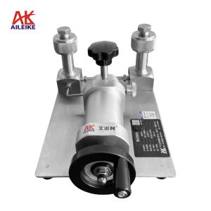
These operating procedures have been drawn up to ensure the accuracy and reliability of pressure gauge measurements and to standardise pressure gauge calibration and testing operations. These procedures utilise the ALKD20 automatic pneumatic calibration bench to carry out full-range testing of both pressure and vacuum for the Y-100BF stainless steel pressure gauge. Operations must be carried out in a disturbance-free environment maintained at a constant temperature of (20±2) °C and constant humidity. In accordance with standards, the instrument must be securely sealed, and stepwise pressure ramp-up and ramp-down calibration must be performed. The requirement to tap the case lightly before taking a reading must be strictly adhered to, and data from each test point must be accurately recorded, with the indication error calculated. During operation, switching under pressure is strictly prohibited; pressure must be increased and decreased gradually to avoid pressure surges, and equipment maintenance must be carried out in accordance with the prescribed schedule. Standardised calibration and measurement ensure that the measured values are accurate and compliant.
I. Pressure Gauge Calibration Tools
|
Name |
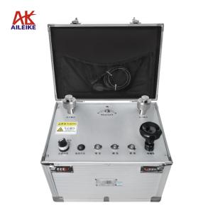
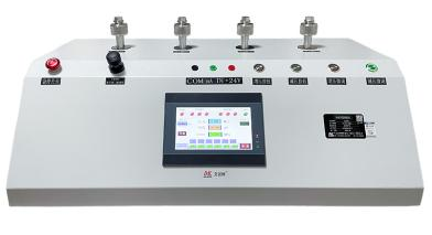
Automatic Barometric Pressure Calibration Stand |
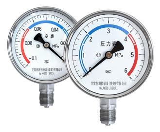
Stainless steel pressure gauge |
|
Model |
ALKD20 |
Y-100BF |
|
Technical Specifications |
Pressurisation method: Manual Pressure range: -0.095 to 6 MPa; Current: 0 to 20 mA Medium: Clean air Outlets: 4; Connection: M20×1.5 (F) Accuracy: Pressure: 0.05% F.S.; Current: 0.05% F.S. Resolution: Pressure: 1 Pa; Current: 1 μA DC voltage output: 24 VDC Communication method: RS485 Modbus protocol Pressure setting: Up to 6 pressure switching values can be set simultaneously Power consumption: <500 VA Drift: <0.01% F.S. per year Pressure fluctuation range: 0.05% F.S. over 5 s Power supply: AC 220 ±10%, 50 Hz Weight: 32 kg Dimensions: 800 × 440 × 400 mm
|
Pressure: -0.1 to 0 MPa / 0 to 6 MPa Accuracy: Class 1.6 Material: Stainless steel Dial diameter: φ100 mm Connection: M20×1.5(M) Net weight: 0.35 kg Product dimensions: 100 × 42 × 140 mm
|
|
Product Dimensions |
|
|
The entire verification process must be carried out in strict accordance with current metrological technical specifications. The main references include: JJG52-2013 ‘General Pressure Gauges, Pressure-Vacuum Gauges and Vacuum Gauges with Elastic Elements’, which applies to the initial verification, periodic verification and in-service inspection of general pressure gauges, pressure-vacuum gauges and vacuum gauges with elastic elements, and covers on-site indicating pressure measuring instruments commonly used in industry.
II. Detailed Explanation of the Operational Process
(1) Preliminary Preparations
1. Environmental Requirements
The temperature must be maintained at (20±2) °C, with relative humidity ≤ 85% RH and no condensation. The site must be free from vibration, dust and corrosive gases.
2. Connecting the Equipment
Connect the pressure gauge under test (Y-100BF) to the outlet of the ALKD20 automatic pneumatic calibration unit using a sealed connection; secure any unused outlets with plugs. Connect the calibration unit to a 220 V power supply and switch it on.
(2) Pneumatic Calibration Procedure for the Pressure Gauge
1. Pressure Build-up Procedure
• First, press the selector valve on the automatic pneumatic calibration unit downwards (do not switch whilst under pressure), then set six pressure values by clicking the input fields for Settings 1 to 6 in turn and entering 0 MPa, 1 MPa, 1.6 MPa, 2.5 MPa, 4 MPa and 6 MPa respectively.
• Once the six pressure values have been set, commence the pressure ramp-up calibration.
• First, select the calibration pressure value of 1 MPa, then click ‘Start’. The calibration stand will begin to automatically increase the pressure to 1 MPa. Once the pressure has stabilised and the reading on the calibration stand’s display screen has ceased to fluctuate, check the pressure reading on the pressure gauge under test. Then, gently tap the side of the pressure gauge’s casing with your finger (do not tap the glass or tap forcefully), observe the position of the pointer, and record the reading once it has stabilised after the tap. Use the reading after tapping as the actual calibration reading for that pressure point, and calculate the error.
• Next, select the second pressure value of 1.6 MPa; the calibration stand will automatically increase the pressure to 1.6 MPa. Once the pressure has stabilised, tap the pressure gauge under test and record the reading.
• Repeat the same procedure, increasing the pressure to 2.5 MPa, 4 MPa and 6 MPa. Check the pressure reading on the pressure gauge under test, tap the gauge, and record the reading once it has stabilised.
2. Depressurisation process
• Select the pressure value of 4 MPa; the calibration bench will begin to depressurise automatically to 4 MPa. Once the pressure has stabilised, tap the pressure gauge under test and record the reading.
• Repeat the same procedure for the calibration points 2.5 MPa, 1.6 MPa and 1 MPa. Observe the pressure reading on the pressure gauge under test, tap the gauge, and record the reading once it has stabilised after tapping.
3. Depressurisation Process
Finally, select a pressure value of 0 MPa; the calibration bench will automatically depressurise to 0, and the measurement will be complete.
(III) Vacuum Calibration Process for Pressure Gauges
1. Pressurisation Process
• First, remove the pressure gauge under test for positive pressure and fit the one for negative pressure; pull the positive/negative pressure switch valve outwards (do not switch whilst under pressure).
• Next, switch the calibration bench to vacuum mode: first tap ‘Parameter Settings’, then enter the password and tap ‘Confirm’; once in the parameter settings interface, tap ‘Back’, then tap the ‘Air Pressure’ button on the screen to switch to vacuum mode.
• Next, set the six vacuum values by tapping the input fields for Settings 1 to 6 in sequence and entering 0 MPa, -0.02 MPa, -0.04 MPa, -0.06 MPa, -0.08 MPa and -0.095 MPa respectively.
• Once the six pressure values have been set, commence the vacuum calibration.
• First, select the calibration vacuum value of -0.02 MPa, then tap ‘Start’. The calibration bench will automatically evacuate the chamber to a vacuum of -0.02 MPa. Once the pressure has stabilised and the reading on the calibration bench’s display screen has ceased to fluctuate, check the pressure reading on the pressure gauge under test. Then, gently tap the side of the pressure gauge’s casing with your finger (do not tap the glass or tap forcefully), observe the position of the pointer, and record the reading once it has stabilised after the tap. Use the reading after tapping as the actual calibration reading for that pressure point, and calculate the error.
• Next, select the second pressure value, -0.04 MPa; the calibration stand will automatically evacuate to a vacuum of -0.04 MPa. Once the pressure has stabilised, tap the pressure gauge under test and record the reading.
• Repeat the same procedure, pumping down to pressure values of –0.06 MPa, –0.08 MPa and –0.095 MPa. Check the pressure reading on the pressure gauge under test, tap the gauge, and record the reading once it has stabilised.
2. Depressurisation process
• Set the vacuum level to –0.08 MPa; the calibration bench will begin to reduce the pressure automatically. Once the pressure has stabilised at –0.08 MPa, tap the pressure gauge under test and record the reading.
• Repeat the same procedure for vacuum values of –0.06 MPa, –0.04 MPa and –0.02 MPa. Observe the pressure reading on the pressure gauge under test, tap the gauge, and record the reading once it has stabilised.
3. Pressure Relief Process
Finally, select a pressure value of 0 MPa; the calibration bench will automatically reduce the pressure to 0, and the measurement will be complete.
III. Precautions
Proper Use
• When switching between pressure and vacuum, do not switch whilst the system is under pressure.
• Connect the ALKD20 automatic pressure calibration unit to a 220V power supply; ensure the connection is correct, and the current measurement must not exceed 22mA.
• Operate in accordance with standard procedures; pressurisation and depressurisation of the ALKD20 automatic pressure calibration unit must be carried out slowly to avoid pressure surges.
• Pressurise to the calibration point and record the reading once the calibrator’s reading has stabilised; for the pressure gauge under test, once the pressure has stabilised, tap the case lightly and take the reading immediately after tapping to ensure accuracy.
• Upon completion of the test, first slowly depressurise to zero and ensure there is no residual pressure; switch off the power supply to the equipment before removing the instrument under test.
Maintenance and Calibration Intervals
• The automatic pneumatic calibration stand should be installed in a temperature-controlled environment.
• The lubricating oil in the automatic pneumatic calibration stand should be checked and replaced every six months or after 500 hours of operation.
• Unless you possess the relevant technical skills and appropriate testing equipment, do not open the unit’s cover to carry out maintenance; under no circumstances should you adjust or replace any components.
• If the automatic barometric pressure calibration bench is to be left unused for an extended period, it must be depressurised before storage and covered with a cloth cover to prevent dust from entering the instrument.
IV. Conclusion
This specification sets out the standardised procedures for the full-range barometric and vacuum calibration of the Y-100BF stainless steel pressure gauge, covering operational requirements for all stages, including environmental control, instrument sealing and connection, and stepwise pressure ramping tests. Strict adherence to operational guidelines—such as tapping the case to read the value, switching to pressure-free mode, and gradually increasing or decreasing pressure—can effectively minimise operational deviations and ensure the accuracy of pressure gauge test data. Combined with regular maintenance and periodic servicing of the calibration bench, this approach maintains the stable metrological performance of the equipment, ensuring that the traceability of pressure gauge measurement results is accurate and compliant, thereby providing robust and reliable metrological technical support for routine metrological management and production operation control.
Related News