

Operational Specifications for the Calibration, Testing and Measurement of Pressure Transmitters (HART Protocol)
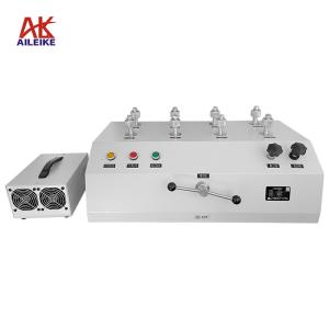
To ensure the accuracy and reliability of pressure measurement in industrial settings, pressure transmitters (HART protocol) must undergo regular calibration, testing and measurement. This specification utilises the ALKD60 automatic hydraulic calibration bench and the ALK475TREX (Chinese version) HART handheld communicator to perform a full calibration process under standardised conditions characterised by strict temperature and humidity control, and the absence of vibration and corrosion. The procedure covers environmental preparation, circuit wiring, zero-point calibration, as well as full-range pressure ramp-up and ramp-down point-by-point verification. This enables precise verification of the linear relationship between pressure values and current output, and the correction of zero-point and span deviations. Operational procedures must be strictly adhered to, with readings taken point by point once values have stabilised, to ensure that measurement data is accurate and reliable and that traceability of measurement values is assured, thereby providing robust data support for industrial measurement and control.
I. Tools for Calibrating Pressure Transmitters (HART Protocol)
|
Name |
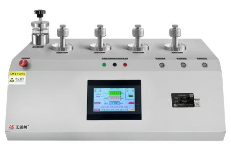
Automatic Hydraulic Calibration Bench |
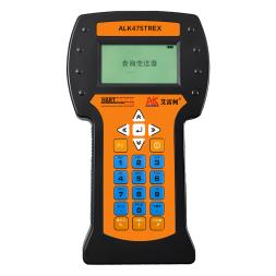
HART Handheld Terminal |
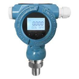
Pressure transmitters |
|
Model |
ALKD60 |
ALK475TREX (Chinese version) |
Various models |
|
Technical Specifications |
Pressure range: 0–60 MPa Medium: Calibration oil Outputs: 4 Connection: M20×1.5(F) Current: 0–20 mA Accuracy: Pressure: 0.05% F·S Current: 0.05% F·S Resolution: Pressure: 1 kPa Current: 1 μA DC voltage output: 24 VDC Communication protocol: RS485 Modbus protocol Pressure setting: 6 pressure switching values can be set simultaneously Power consumption: <500 VA Drift: < 0.01% F.S. per year Pressure fluctuation range: 0.05% F.S. over 5 s Power supply: AC 220 ±10%, 50 Hz Weight: 46.5 kg Dimensions: 800 × 440 × 470 mm
|
Communication: HART protocol Display: Monochrome screen Language: Chinese DC output: 24V DC Power supply: Built-in rechargeable battery Net weight: 0.5kg Dimensions: 230×130×45mm
|
Pressure: 0–60 MPa Accuracy: ±0.1% FS ±0.2% FS ±0.5% FS Output signal: 4–20 mA + HART Power supply: 24 V DC Connection: M20×1.5(M)
|
|
Product Dimensions |
|
|
|
The entire verification process must be carried out in strict accordance with current metrological technical specifications. The main references include: JJG 882-2019 ‘Pressure Transmitters’, which applies to the verification, periodic calibration and in-service inspection of pressure transmitters, and is used to standardise the indication error, hysteresis and repeatability of transmitters.
II. Detailed Explanation of the Operational Process
(1) Preliminary Preparations
1. Environmental Requirements
The temperature must be maintained at (20±2) °C, with relative humidity ≤ 85% RH and no condensation. The site must be free from vibration, dust and corrosive gases.
2. Filling, pressurising and priming the automatic hydraulic calibration bench
• Prepare the pressure transmission medium (calibration oil).
• Unscrew the pressure relief valve on the fluid reservoir and fill the reservoir with the medium. Ensure a sufficient quantity is added; once filling is complete, refit the pressure relief valve.
3. Connecting the Equipment
• Make a sealed connection between the pressure transmitter (HART protocol) and the output port of the ALKD60 automatic hydraulic calibration bench. Secure any unused output ports with plugs. Connect the calibration bench to a 220V power supply and switch it on.
• Wiring Method 1 (24 V power supply from the automatic hydraulic calibration unit):
(1) Red test lead connection: Insert one end into the calibration unit’s 24 V socket and clamp the other end to the transmitter’s positive terminal.
(2) Connect the transmitter’s negative terminal to a 250 Ω resistor.
(3) Black test lead connection: Insert one end into the calibration unit’s current socket and clamp the other end to one side of the 250 Ω resistor.
(4) Handheld communicator communication cable connection: Insert one end into the handheld communicator’s communication port, and clip the other end to both ends of the 250Ω resistor
(5) Once the connections are complete, a closed circuit is formed
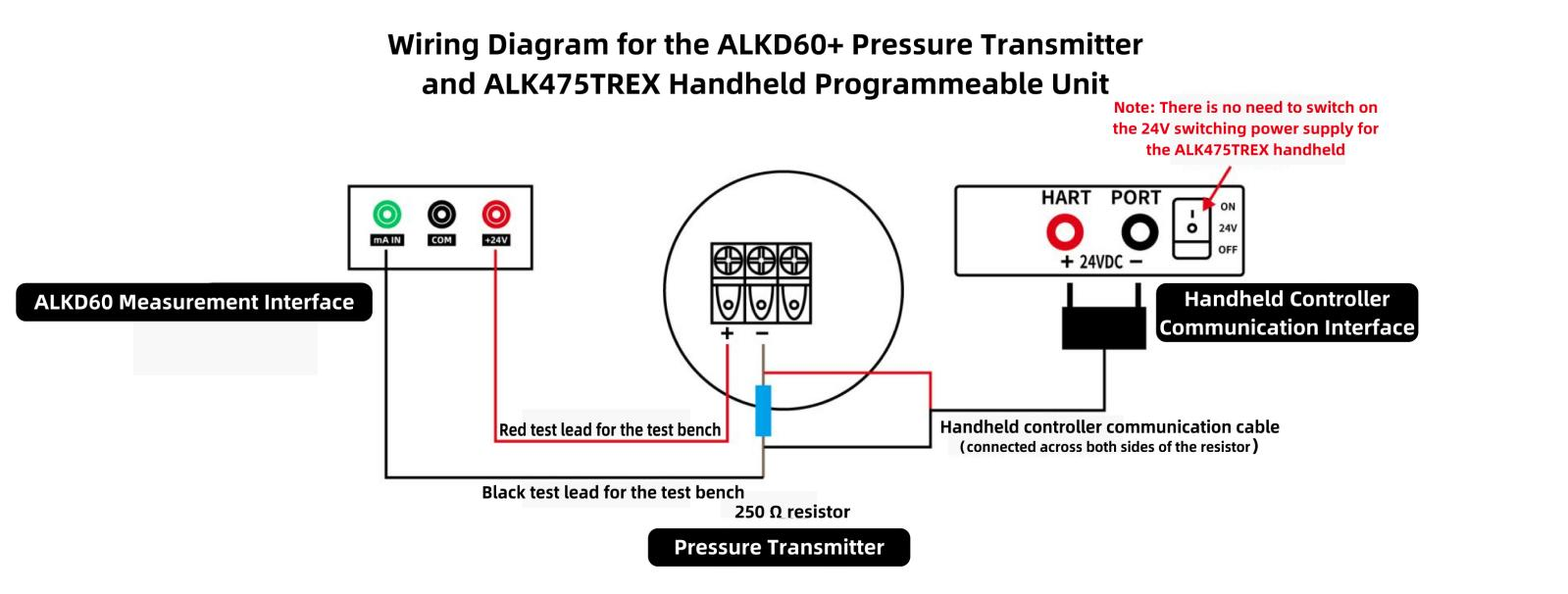
Wiring Diagram (1)
• Wiring Method 2 (ALK475TREX handheld unit powered by 24 V):
(1) Red test lead connection: Insert one end into the current socket on the calibration bench; clip the other end to the negative terminal of the transmitter
(2) Black test lead connection: Insert one end into the common terminal socket on the calibration bench
(3) Handheld unit communication cable connection: Insert one end into the communication port on the handheld unit; clip the red clamp to the positive terminal of the transmitter, and clip the black clamp together with the clamp on the black test lead from the calibration bench
(4) Once the connections are complete, forming a closed circuit, switch on the 24V switching power supply for the ALK475TREX handheld unit
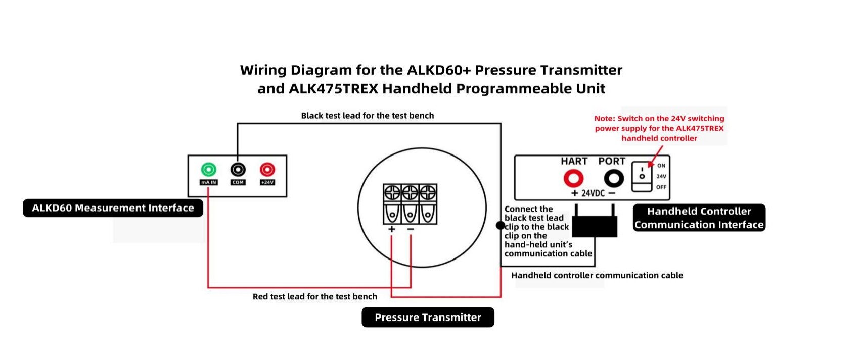
Wiring Diagram (2)
• If the transmitter does not display zero at the current atmospheric pressure, and the calibration bench detects a deviation in the transmitter’s 4 mA current reading, use a HART handheld communicator to calibrate the transmitter’s zero point and current.
4. Specific calibration steps using the handheld communicator
(1) Calibrating the transmitter’s zero point
Switch on the handheld communicator; the handheld communicator has successfully established communication with the pressure transmitter.
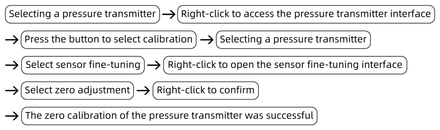
(2) Calibrate the 4 mA or 20 mA current output from the transmitter as measured by the pressure gauge
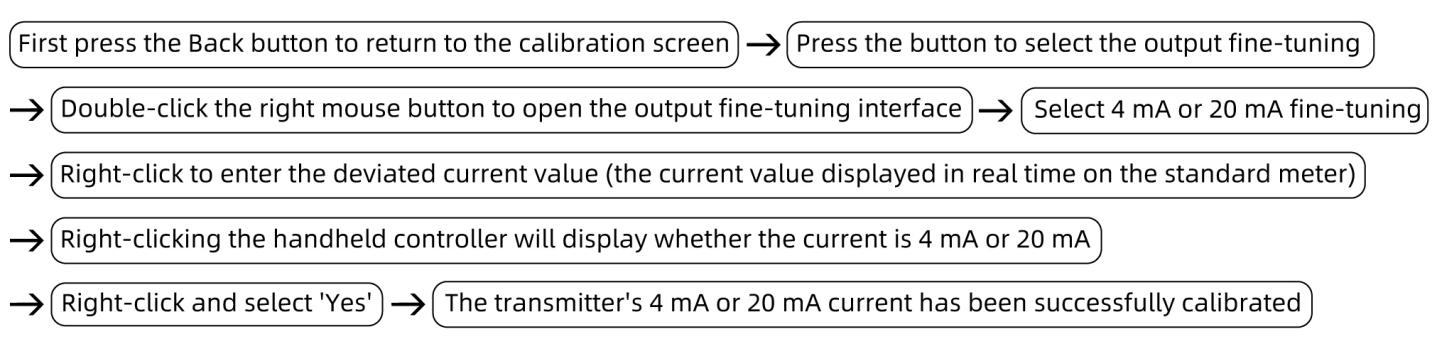
(2) Verification and Calibration Procedure for Pressure Transmitters (HART Protocol)
1. Set six pressure values
• First, set the six verification pressure values for the ALKD60 automatic hydraulic calibration bench. Click the input fields for Settings 1 to 6 in turn and enter 0 MPa, 12 MPa, 24 MPa, 36 MPa, 48 MPa and 60 MPa respectively.
• Once the six pressure values have been set, close the pressure relief valve.
2. Pressure Increase and Calibration Process
• Press the ‘Set’ button to select the calibration pressure of 12 MPa, then press the ‘Start’ button; the calibration bench will begin to increase the pressure automatically. If there is a deviation when reaching the calibration pressure of 12 MPa, or if the current value measured by the calibration bench for the transmitter (7.2 mA) also shows a deviation, use the handheld calibrator to adjust the pressure and current values.
• Calibrating the transmitter’s pressure value:
Select ‘Low Range Fine-Tuning’ or ‘High Range Fine-Tuning’. If the pressure value measured by the transmitter is below 12 MPa, select ‘Low Range Fine-Tuning’; if the pressure value is above 12 MPa, select ‘High Range Fine-Tuning’. Then press the right key, enter the pressure value of 12 MPa, and finally press the right key again to confirm. The pressure and current values will then be successfully calibrated simultaneously.
• Continue by pressing the ‘Set’ button to calibrate the pressure value of 24 MPa. The calibration bench will automatically pressurise to 24 MPa; if there is a deviation, the current value measured by the calibration bench should be 10.4 mA. Should there be an error, calibrate using the handheld controller (follow the procedure described above).
• Repeat the same procedure, increasing the pressure to 36 MPa, 48 MPa and 60 MPa. The calibration stand should measure current values of 13.6 mA, 16.8 mA and 20 mA respectively from the transmitter. If any errors are detected, calibrate using the handheld controller (follow the procedure described above).
3. Depressurisation Calibration Process
• Select a pressure value of 48 MPa; the calibration bench will begin to reduce the pressure automatically. If there is a deviation when the pressure is reduced to the calibration value of 48 MPa, and the current value measured by the calibration bench (16.8 mA) also shows a deviation, use the handheld calibrator to adjust both the pressure value and the current value.
• Repeat the same procedure to reduce the pressure to 36 MPa, 24 MPa and 12 MPa. The calibration bench should measure current values of 13.6 mA, 10.4 mA and 7.2 mA respectively from the transmitter. If any deviations are detected, use the handheld calibrator to correct the pressure and current values (follow the procedure described above).
4. Pressure Relief Process
Select a pressure value of 0 MPa; the calibration bench will automatically reduce the pressure to 0. When the calibration bench stops operating and the lights for the pressure relief and reset buttons illuminate, finally open the pressure relief valve to reduce the pressure to 0, at which point the measurement is complete.
III. Precautions
Proper Use
• The pressure-transmitting medium must be clean and free from impurities to prevent blockages in the pipework and damage to the automatic hydraulic calibration bench.
• The automatic hydraulic calibration bench is connected to a 220V power supply; ensure the connection is correct, and the current measurement must not exceed 22mA.
• Operations must follow standard procedures, increasing and decreasing pressure point by point to avoid pressure surges.
• Ensure that the communication cable between the calibration bench and the handheld controller, as well as the pressure transmitter wiring, are correctly identified; take great care to prevent reverse connections.
• Readings at calibration points must be taken only after the value on the standard gauge has stabilised; ensure that records are accurate and up-to-date.
• Upon completion of the test, first slowly depressurise the system to zero, ensuring there is no residual pressure, then switch off the power supply to the equipment before removing the instrument under test.
Maintenance and Calibration Intervals
• The oil reservoir of the automatic hydraulic calibration bench must not come into contact with highly volatile substances such as alcohol, xylene or diethyl ether.
• The automatic hydraulic calibration bench should be installed in a temperature-controlled environment.
• If the automatic hydraulic calibration bench is to be left unused for an extended period, it must be depressurised before storage; the liquid in the reservoir must be drained and the unit covered with a cloth cover to prevent dust from entering the instrument.
IV. Conclusion
Completing the full calibration procedure enables the performance testing and precise calibration of pressure transmitters (HART protocol), effectively correcting zero-point and span deviations, and verifying the linear relationship between pressure input and current output. Strict adherence to the operational procedures of incrementally increasing and decreasing pressure point by point, and taking readings only after values have stabilised, ensures that measurement data is accurate and traceable, guaranteeing the precision and reliability of the transmitter’s output across the full range.
Related News