

Operational Procedures for the Calibration and Testing of Resistance Temperature Detectors Across the Full Temperature Range, and Equipment Maintenance Guidelines
This standardised operating procedure has been drawn up to standardise the calibration and testing of resistance temperature detectors, to ensure the accurate and reliable traceability of temperature measurements, and to guarantee that the performance of temperature measurement equipment complies with current metrological technical specifications. For this calibration, the Aileko ALKW851A dry-block temperature calibration oven is used as the constant-temperature source, in conjunction with the ALKWZP-T1000 digital thermometer and the ALKH513 Thermal Performance Handbook, to carry out indication testing of the PT100 thermoresistor across the full temperature range from –20 °C to 150 °C. Environmental conditions were strictly controlled throughout the calibration process; equipment wiring was standardised; temperature ramp-up and ramp-down tests were carried out in accordance with the specified temperature gradient; data was read and recorded once the temperature had stabilised; and operational procedures and equipment maintenance requirements were strictly adhered to. This ensured that the calibration process was compliant and that the data was accurate and traceable, thereby providing reliable support for the stable operation of industrial temperature measurement systems.
I. Tools for Calibrating Resistance Temperature Detectors
|
Name |
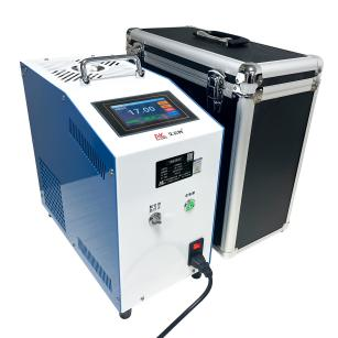
Dry-block temperature calibration oven |
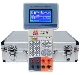
The Thermodynamics Handbook |
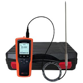
Digital thermometer |
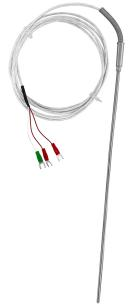
Thermoresistor |
|
Model |
ALKW851A |
ALKH513 |
ALKWZP-T1000 |
Various models |
|
Technical Specifications |
Temperature range: -20 to 150 °C Control method: LCD touchscreen Instrument accuracy: Class 0.1 Measuring hole diameters: φ6 mm, φ8 mm, φ10 mm, φ12 mm Default display: Chinese/English switch Power supply: 220 V, 50 Hz, 600 W Weight: 12.7 kg Furnace dimensions: 360 × 190 × 380 mm
|
Signal output: DC current, DC voltage, RTD, thermocouple, frequency, loop-powered Accuracy: Class 0.05 Power supply: Built-in rechargeable battery Net weight: 0.7 kg Dimensions: 235 × 130 × 50 mm
|
Resolution: 0.001°C Temperature range: -200 to +800°C Calibration method: Multi-point calibration Probe length: 245 mm Probe diameter: φ4 mm Net weight: 0.25 kg Dimensions: 170 × 73 × 40 mm
|
Model No.: PT100 Temperature measurement range: -20 to +150 °C Protective tube: Stainless steel Net weight: 0.1 kg Dimensions: L = 300 × 1500 mm
|
|
Product Dimensions |
|
|
|
|
The entire verification process must be carried out in strict accordance with current metrological technical specifications, the main references for which include:JJG 229-2010 ‘Industrial Platinum and Copper Resistance Thermometers’, which applies to industrial platinum resistance thermometers with a nominal temperature coefficient α of 3.851 × 10⁻³ °C⁻¹ for use within the range of –200 °C to +850 °C, and to industrial copper resistance thermometers for use within the range of –50 °C to +150 °C; it applies to initial verification, subsequent verification and in-service inspections.
II. Detailed Explanation of the Operational Process
(1) Preliminary Preparations
1. Environmental Requirements
The temperature must be maintained at (20±2) °C, with relative humidity ≤ 85% RH and no condensation. The site must be free from vibration, dust and corrosive gases.
2. Connecting the equipment
• First, place the PT probe of the ALKWZP-T1000 digital thermometer into the hole in the homogenisation block of the dry-block temperature calibration furnace. Next, set the ALKH513 Thermal Engineering Handbook to measure a PT100 thermoresistor, and then place the thermoresistor into the hole in the homogenisation block of the dry-block temperature calibration furnace.
• Wiring of the Thermal Engineering Handbook test probes:
(1) Insert the red test probe into the Thermal Engineering Handbook’s thermoresistor measurement socket; clip the other end of the red alligator clip onto the two red terminals of the thermoresistor.
(2) Insert the black test probe into the Thermal Engineering Handbook’s common terminal; clip both ends of the black alligator clip onto the green terminals of the thermoresistor.
(3) All equipment is now successfully connected.
(2) Operating Procedure for Heating and Cooling Modes of the Dry-Block Oven
1. Heating Mode Procedure
• First, use lint-free cotton wool to plug the unused holes in the heat-distribution block; the cotton wool helps to minimise heat loss and maintain a stable temperature inside the oven.
• Next, access the screen of the dry-block temperature calibration oven, select ‘Set Temperature’, enter the calibration value of 50 °C, then press the ‘Heat’ button. Turn the knob to the heating mode, whereupon the calibration oven will begin to heat up automatically. When the temperature reaches 50°C, the Thermal Engineering Handbook and the digital thermometer both measure a temperature of 50°C for the RTD, whilst the Thermal Engineering Handbook measures a corresponding resistance value of 119.40 Ω.
• Continue by pressing the ‘Set Temperature’ button and entering 100°C. The dry-block temperature calibration oven continues to heat automatically. When the temperature reaches 100°C, both the Thermal Engineering Handbook and the digital thermometer measure the temperature of the RTD as 100°C, whilst the Thermal Engineering Handbook measures the corresponding resistance value as 138.50 Ω.
• Following the same procedure, enter the next temperature value of 150°C. The dry-block temperature calibration oven heats up automatically; when the temperature reaches 150°C, both the Thermal Engineering Handbook and the digital thermometer measure the temperature of the thermocouple as 150°C, and the Thermal Engineering Handbook measures the corresponding resistance value as 157.32 Ω.
2. Cooling Mode Procedure
• First, allow the dry-block temperature calibration oven to cool naturally to room temperature before operating in cooling mode.
• Once the dry-block temperature calibration oven has cooled to room temperature, press the ‘Set Temperature’ button, enter the temperature to be calibrated (0 °C), press the ‘Cooling’ button, and then turn the knob to the ‘Cooling’ mode; the calibration oven will then begin to cool automatically. When the temperature reaches 0 °C, both the Thermal Engineering Handbook and the digital thermometer measure the temperature of the RTD as 0 °C, whilst the Thermal Engineering Handbook measures the corresponding resistance value as 99.98 Ω.
• Continue by entering the next temperature value, –10 °C. The dry-block temperature calibration oven will cool down automatically. When the temperature reaches –10 °C, both the Thermal Engineering Handbook and the digital thermometer will measure a temperature of –10 °C for the thermoresistor, whilst the Thermal Engineering Handbook will measure a corresponding resistance value of 96.07 Ω.
• Following the same procedure, enter the next temperature value of –20 °C. The dry-block temperature calibration oven automatically cools down; when the temperature reaches –20 °C, both the Thermal Engineering Handbook and the digital thermometer read a temperature of –20 °C for the RTD, and the Thermal Engineering Handbook measures a corresponding resistance value of 92.14 Ω.
3. Procedure upon completion of measurements
• Once measurements at all temperature points have been completed, wait until the cooling cycle has finished and the calibration oven has returned to room temperature before switching off the power supply.
• Press the ‘Stop’ button, then turn the knob to the ‘Stop’ position; the calibration oven will begin to warm up naturally. Once the calibration oven has returned to room temperature, switch off the fan power supply to complete the measurement.
III. Precautions
Proper Use
• In the high-temperature calibration section, do not touch the heat-distribution block or the interior of the furnace directly; in the low-temperature calibration section, do not touch low-temperature components with bare hands, to avoid skin burns or frostbite.
• Before switching on the power, ensure that the supply voltage matches the equipment’s rated voltage to prevent electrical faults.
• The probe of the digital thermometer and the RTD must be fully inserted into the holes in the heat-distribution block to ensure full contact with it.
• Ensure that the wiring between the Thermal Engineering Handbook ALKH513 and the RTDs is clearly identified to strictly prevent incorrect connections.
• Only switch on the power once all wiring has been completed and verified as correct; do not connect or disconnect test leads or probes whilst the equipment is powered on.
• At each calibration temperature point, wait until the furnace temperature has stabilised and the readings on the digital thermometer and the Thermal Engineering Handbook no longer fluctuate before reading and recording the values.
Maintenance and Calibration Intervals
• Carry out periodic metrological verification of the ALKW851A dry-block temperature calibration furnace, the ALKH513 Thermal Engineering Handbook and the ALKWZP-T1000 digital thermometer to ensure accurate traceability of measurement values.
• Switch off the power supply when the calibration equipment is not in use; if the Thermal Engineering Handbook is not used for an extended period, it should be charged once every three months.
• When calibration equipment is not in use for extended periods, cover it with a dust cover to prevent dust from entering the instrument.
IV. Conclusion
Completing calibration and testing across the full temperature range from –20 °C to 150 °C enables systematic verification of the accuracy and temperature range stability of PT100 thermistors, providing objective and traceable data support for equipment conformity assessment, on-site commissioning and periodic re-verification. Strict adherence to this procedure during operation effectively mitigates measurement errors caused by environmental interference, wiring deviations and thermal shock losses, thereby ensuring the validity of test results and metrological traceability. Proper daily maintenance of the calibration equipment and periodic metrological verification will sustain the instrument’s metrological performance over the long term, laying a solid technical foundation for the full lifecycle quality control of thermistors in industrial settings and the stable operation of temperature measurement systems.
Related News