

Detailed explanation of the operation process for pressure measurement and calibration of digital display differential pressure transmitters
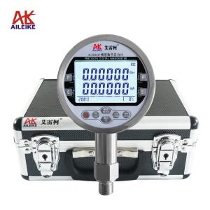
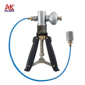
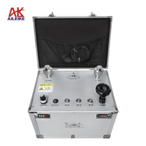
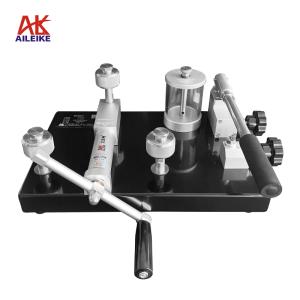
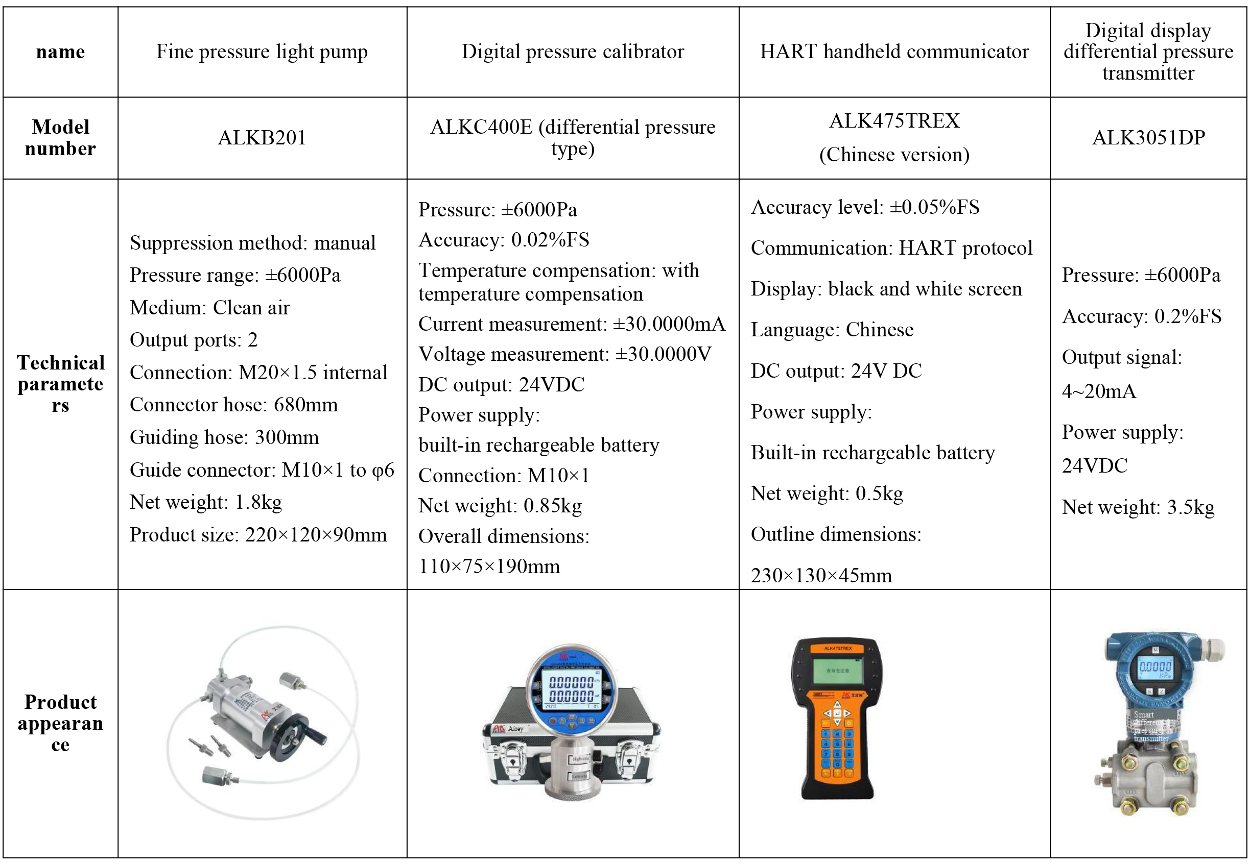
The differential pressure transmitter is a core pressure detection instrument in the field of industrial process measurement and control. Its measurement accuracy and output stability affect the accuracy of operating condition parameter monitoring, process control, and data metering. To ensure the accuracy and compliance of instrument measurements, calibration and testing work must be carried out in accordance with specifications. This calibration targets the ALK3051DP differential pressure transmitter, relying on the micro pressure light pump ALKB201, the differential pressure digital pressure calibrator ALKC400E, and the HART handheld device ALK475TREX to build a standard testing system. The system covers the full range of positive and negative pressures, completing zero point calibration, range point calibration, and pressure rise and fall return difference verification. The correspondence between pressure and current is verified through standard comparison and parameter fine adjustment. Standard calibration and regular maintenance can ensure that the metering performance of the instrument meets standards.
1. Calibration tool for differential pressure transmitter
The entire verification process must strictly adhere to the current metrological technical specifications. The main references include: JJG 882-2019 "Pressure Transmitter", which is applicable to the verification, periodic calibration, and in-service inspection of pressure transmitters. It is used to standardize the verification of the transmitter's indication error, hysteresis, and repeatability.
II. Detailed Explanation of Operational Procedures
(I) Preliminary preparations
1. Environmental requirements
The temperature should be controlled at (20±2)℃, with a relative humidity of ≤85%RH, and there should be no condensation. Ensure that the site is free from vibration, dust, and corrosive gases.
2. Tool connection
• Connect the differential pressure transmitter ALK3051DP and the digital pressure calibrator ALKC400E (differential pressure type, hereinafter referred to as differential pressure gauge) in a sealed manner to the output port of the micro-pressure light pump ALKB201.
(1) The high-range interface of the differential pressure gauge is connected to one of the output ports of ALKB201.
(2) The high-range interface of the differential pressure transmitter is connected to another output port of ALKB201.
• Wiring method 1 (digital pressure calibrator 24V power supply):
(1) Wiring of the red test line: Insert one end into the 24V interface of the standard meter, and clamp the other end onto the positive terminal of the transmitter
(2) Connect the transmitter's negative terminal to a 250Ω resistor
(3) Wiring of black test line: Insert one end into the current interface of the standard meter, and clamp the other end onto one side of a 250Ω resistor
(4) Wiring of the handheld communicator communication cable: One end is plugged into the communication interface of the handheld communicator, and the other end is clipped to both ends of a 250Ω resistor
(5) Complete the wiring to form a closed circuit
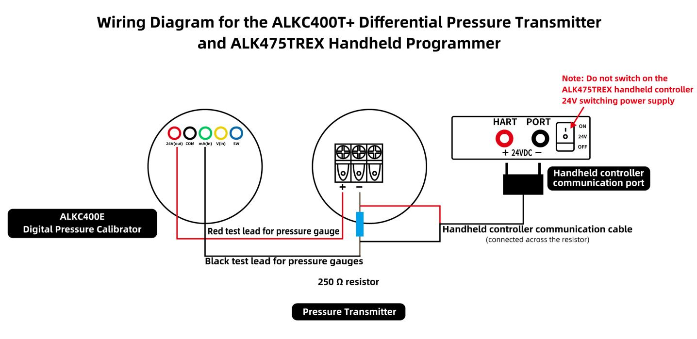
Wiring diagram (I)
• Wiring method 2 (ALK475TREX handheld device 24V power supply):
(1) Wiring of the red test line: Insert one end into the current interface of the standard meter, and clamp the other end onto the negative terminal of the transmitter
(2) Connection of black test line: Insert one end into the common terminal interface of the standard meter
(3) Wiring of the handheld communicator communication cable: Plug one end into the handheld communicator communication interface, clip the red clip onto the transmitter's positive terminal, and clip the black clip together with the clip of the black test line
(4) Complete the wiring to form a closed circuit, and turn on the 24V switch power supply of the ALK475TREX handheld device
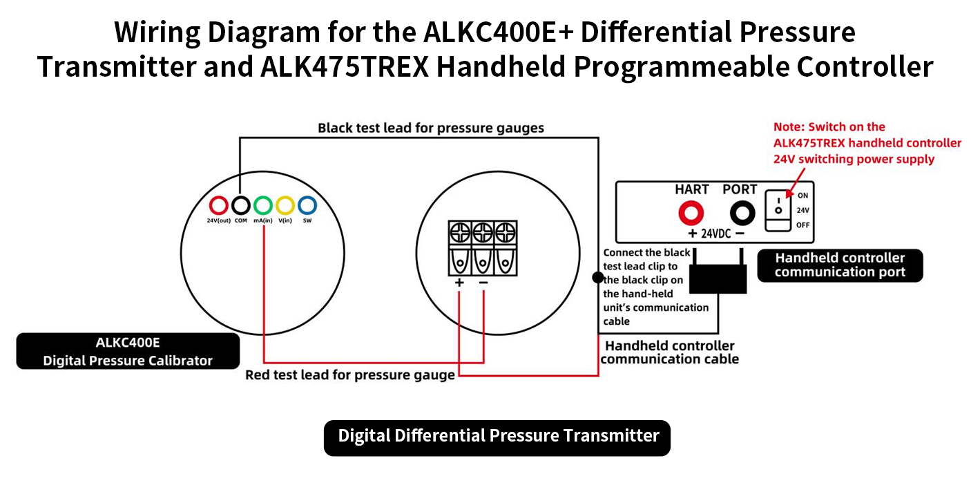
Wiring diagram (II)
• If the differential pressure transmitter indicates a value other than 0 under current atmospheric pressure, indicating a deviation in the current value of 12mA measured by the standard meter, then take out the HART handheld device to calibrate the transmitter's zero point and current.
(II) Positive pressure calibration process of differential pressure transmitter
1. Voltage boost calibration process
First, turn the ALKB201 handle counterclockwise to the appropriate position, then turn the precision adjustment knob counterclockwise to the appropriate position, and finally close the pressure relief valve.
• Then, use the handle to gradually apply pressure clockwise until it reaches around the verification value, and then use the precision fine adjustment to adjust clockwise to the verification value of 3000Pa. If there is a deviation, the current value of the differential pressure transmitter measured by the differential pressure gauge is also 16mA, which also has a deviation. Take out the handheld calibrator to calibrate the pressure value and current value.
• Calibrate transmitter pressure value:
Select low-range trimming or high-range trimming. When the pressure value measured by the transmitter is below 3000Pa, select low-range trimming; when the pressure value is above 3000Pa, select high-range trimming. Then press the right button, enter the pressure value of 3000Pa, and finally press the right button to confirm. The pressure value and current value are calibrated successfully simultaneously.
• Then, use the handle to gradually apply pressure clockwise, stopping when the pressure reaches around the verification value. Next, use the precision micro-adjustment to adjust it to the verification value of 6000Pa. The current value should be 20mA. If there is an error, calibrate it using the handheld device (as per the above operation).
2. Pressure relief calibration process
• First, use the handle to slowly decrease the pressure counterclockwise, stopping when the pressure is around the verification value. Then, use the precision fine adjustment to adjust it to the verification value of 3000Pa. The current value measured by the differential pressure gauge for the differential pressure transmitter should be 16mA. If there is a deviation, the handheld device needs to be taken out to calibrate the pressure and current values.
Record the correspondence between pressure and current at each point, and verify whether the return difference (current difference at the same point during pressure increase and decrease) meets the requirement (≤0.05%FS).
3. Pressure relief process
Open the pressure relief valve, gradually release the pressure inside the pipeline, and when the pressure relief reaches 0, the measurement is complete.
(III) Differential pressure transmitter negative pressure calibration process
1. Voltage boost calibration process
First, turn the ALKB201 handle clockwise to the appropriate position, then turn the precision micro-adjustment clockwise to the appropriate position, and finally close the pressure relief valve.
• Next, use the handle to apply negative pressure counterclockwise, stopping when the pressure reaches around the verification value. Then, use the precision fine adjustment to adjust counterclockwise to the verification value minus 3000Pa. If there is a deviation between the pressure value measured by the differential pressure transmitter and -3000Pa, and if there is also a deviation in the current value of the differential pressure transmitter measured by the differential pressure gauge, which is 8mA, take out the handheld calibrator to calibrate the pressure and current values.
• Calibrate transmitter pressure value:
Select low-range segment trimming or high-range segment trimming. When the pressure value measured by the transmitter is lower than -3000Pa, select low-range segment trimming; when the pressure value is higher than -3000Pa, select high-range segment trimming. Then press the right button, enter the pressure value as -3000Pa, and finally press the right button to confirm. The pressure value and current value are calibrated successfully simultaneously.
• Then, use the handle to apply negative pressure counterclockwise until it reaches around the verification value, and then use the precision fine adjustment to adjust it to the verification value -6000Pa. The current value should be 4mA. If there is an error, calibrate it with the handheld device (as per the above operation).
2. Pressure reduction calibration process
• First, use the handle to slowly depressurize clockwise, stopping when the pressure reaches around the verification value. Then, use the precision fine adjustment to adjust to the verification value -3000Pa. The current value measured by the differential pressure gauge for the differential pressure transmitter should be 8mA. If there is a deviation, the handheld device needs to be taken out to calibrate the pressure and current values.
Record the correspondence between pressure and current at each point, and verify whether the return difference (current difference at the same point during pressure increase and decrease) meets the requirement (≤0.05%FS).
3. Pressure relief process
Open the pressure relief valve, gradually release the pressure inside the pipeline until it reaches 0, and then the measurement is complete.
III. Precautions
Standardized use
• Operations should follow standard procedures. The ALKB201 micro-pressure light pump should be pressurized and depressurized slowly to avoid pressure shock.
• The wiring of the differential pressure gauge must be clear and unambiguous to strictly prevent reverse wiring.
• The reading of the verification point should be taken after the value of the differential pressure gauge stabilizes, and the record should be kept accurate and real-time.
• After the inspection is completed, slowly release the pressure to zero and ensure there is no residual pressure. Turn off the equipment power supply before removing the inspected instrument.
Maintenance and calibration cycle
• Regularly conduct metrological verification on the digital pressure calibrator ALKC400E (differential pressure type) (it is recommended to do so once a year) to ensure that the measurement accuracy meets the standard.
• When the differential pressure gauge is not in use, the power should be turned off. If it is not used for a long period of time, it should be charged once every three months.
• The micro-pressure light pump should be depressurized and stored with a cloth cover after long-term non-use to prevent dust from entering the instrument.
IV. Conclusion
In this calibration operation of the differential pressure transmitter, bidirectional detection of the full range of positive and negative pressures was completed, verifying the hysteresis characteristics and zero stability of the instrument. The measurement deviation was effectively corrected to ensure that the correspondence between pressure measurement and current output conforms to the metrological standards. Standardized testing procedures and standardized operations are core elements in ensuring accurate and reliable industrial pressure measurement. Coupled with regular metrological verification and daily operation and maintenance management, the metrological performance of the instrument can be sustained, providing solid support for precise monitoring of key parameters such as differential pressure, liquid level, and flow rate on site, and ensuring long-term stable operation of the production system.
Related News