


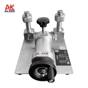
AILEIKE Pressure Transmitter Calibration (HART Protocol) Standardised Operating Guidelines
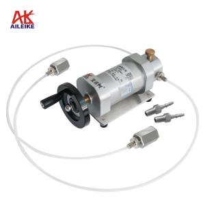
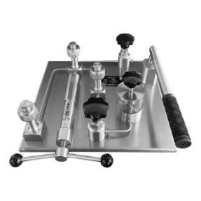
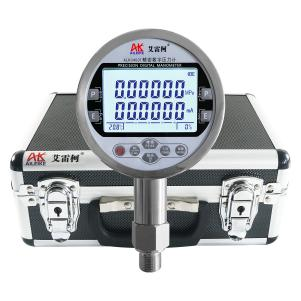
Pressure transmitters (HART protocol) are critical measurement devices in industrial measurement and control. Due to long-term exposure to temperature fluctuations, vibrations, and component aging, they are prone to zero-point drift, deviations in pressure readings, and deviations in the 4–20 mA current signal. To ensure the accuracy of measurement data, periodic standardized calibration is therefore required. This calibration was performed using the ALKT804 hydraulic calibration bench, the ALKC400T precision digital pressure gauge, and the ALK475TREX (Chinese version) HART handheld communicator, in a standard environment maintained at a constant temperature and low humidity, free from dust and vibration. After completing the sealing of the piping and electrical connections, the equipment underwent multi-point calibration involving both pressure increase and decrease. The HART handheld communicator was used to adjust the zero point and range parameters, while simultaneously verifying the instrument’s hysteresis. The process strictly controlled the cleanliness of the pressure-transmitting medium and ensured smooth pressure transitions. Combined with periodic equipment maintenance, these measures guarantee a linear relationship between pressure and output current, controlling measurement errors at the source and ensuring stable and reliable industrial pressure measurement.
I. Tools for Calibrating Pressure Transmitters (HART Protocol)
|
Name |
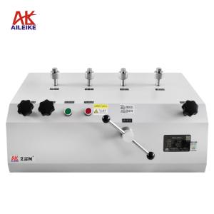
Hydraulic Calibration Stand |
Precision Digital Pressure Gauge |
HART Handheld Programmer |
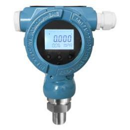
Pressure Transmitters |
|
Model |
ALKT804 |
ALKC400T |
ALK475TREX (Chinese Version) |
Various Models |
|
Technical Specifications |
Pressurization Method: Manual Pressure: 0–100 MPa Medium: Purified water or calibration oil Outlets: 3 Connection: M20×1.5(F) Net Weight: 14 kg Product Dimensions: 410 × 410 × 180 mm
|
Pressure: 0–100 MPa Accuracy: ±0.05% FS Current Measurement: ±30.0000 mA Voltage Measurement: ±30.0000 V DC Output: 24 VDC Communication Interface: RS-232/RS-485 Temperature Compensation: With temperature compensation Power Supply: Built-in rechargeable battery Net Weight: 0.6 kg Connection: M20×1.5 (M) Dimensions: 110×50×185 mm
|
Communication: HART Protocol Display: Black-and-white screen Language: Chinese DC Output: 24V DC Power Supply: Built-in rechargeable battery Net Weight: 0.5 kg Dimensions: 230 × 130 × 45 mm
|
Pressure: 0–100 MPa Accuracy: ±0.1% FS ±0.2% FS ±0.5% FS Output Signal: 4–20 mA + HART Power Supply: 24 VDC Connection: M20×1.5(M)
|
|
Product Dimensions |
|
|
|
|
The entire verification process must strictly comply with current metrological technical specifications. The primary references include: JJG 882-2019 “Pressure Transmitters,” which applies to the verification, periodic calibration, and in-service inspection of pressure transmitters, and is used to standardize the indication error, hysteresis, and repeatability of transmitters.
II. Detailed Explanation of the Operational Process
(1) Preliminary Preparations
1. Environmental Requirements
The temperature must be maintained at (20±2) °C, with relative humidity ≤ 85% RH and no condensation. The site must be free from vibration, dust and corrosive gases.
2. Filling, Pressurizing, and Testing the Hydraulic Test Stand
• Prepare the pressure-transmitting fluid (purified water or calibration oil).
• Unscrew the pressure relief valve on the fluid reservoir and fill the reservoir with the fluid. Once sufficiently filled, reinstall the pressure relief valve and tighten it securely.
• Next, purge excess air from the hydraulic test bench. First, open the pressure-stabilizing valve, the relief valve, and the overpressure shut-off valve. Turn the fine-adjustment knob counterclockwise until it stops. Then, unscrew the plugs from the three outlet ports and close the relief valve. Next, use the lever to pressurize the system, directing the pressure to the three outlet ports.
3. Tool Connection
• Connect the pressure transmitter and the ALKC400T precision digital pressure gauge to two of the ALKT804 output ports using sealed connectors; secure the remaining port with a plug.
• Wiring Method 1 (24V Power Supply for Precision Digital Pressure Gauge):
(1) Red test lead connection: Insert one end into the standard gauge’s 24V port, and clip the other end to the transmitter’s positive terminal
(2) Connect the transmitter’s negative terminal to the 250Ω resistor.
(3) Black test lead connection: Insert one end into the standard meter’s current port, and clip the other end to one side of the 250Ω resistor.
(4) Handheld communicator cable connection: Insert one end into the handheld communicator’s communication port, and clip the other end to both ends of the 250Ω resistor.
(5) Complete the wiring to form a closed loop.
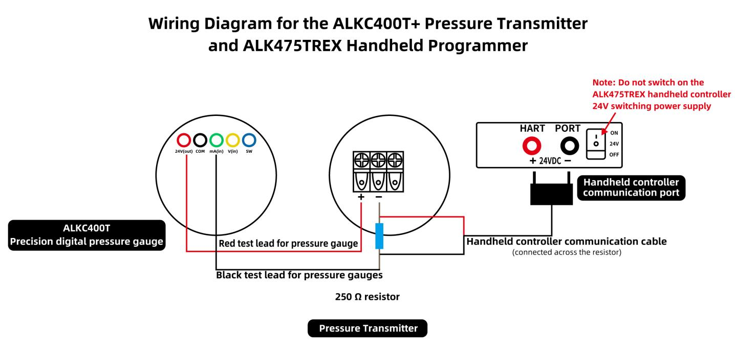
Wiring Diagram (1)
• Wiring Method 2 (ALK475TREX Handheld Transmitter, 24V Power Supply):
(1) Red test lead connection: Insert one end into the standard meter’s current terminal, and clip the other end to the transmitter’s negative terminal.
(2) Black test lead connection: Insert one end into the standard meter’s common terminal.
(3) Handheld unit communication cable connection: Insert one end into the handheld unit’s communication port; clip the red clamp to the transmitter’s positive terminal, and clip the black clamp together with the clamp on the black test lead
(4) Once the connections are complete and a closed circuit is formed, turn on the ALK475TREX handheld unit’s 24V switching power supply
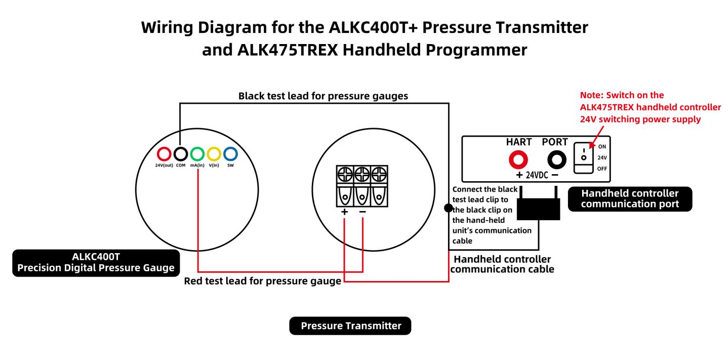
Wiring Diagram (2)
• If the transmitter does not display 0 at the current atmospheric pressure, and the standard manometer indicates a deviation in the transmitter’s 4 mA current value, use a HART handheld communicator to calibrate the transmitter’s zero point and current.
4. Specific Calibration Steps Using the Handheld Communicator
(1) Calibrating the Transmitter’s Zero Point
Turn on the handheld communicator. The handheld communicator has successfully established communication with the pressure transmitter.
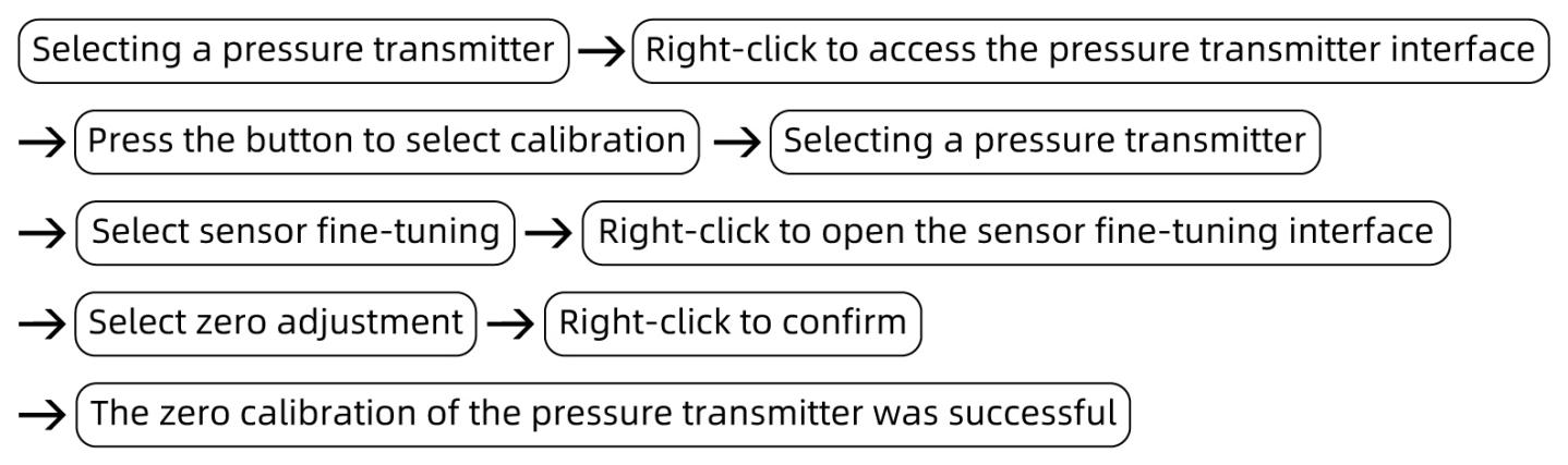
(2) Calibrate the 4 mA or 20 mA current value measured by the pressure gauge from the transmitter
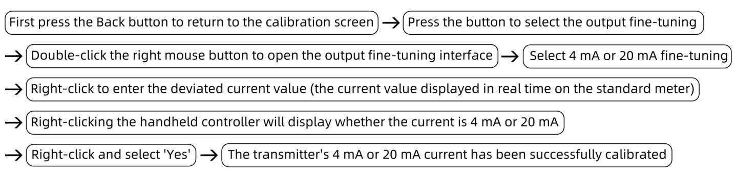
(2) Calibration Process for Pressure Transmitters (HART Protocol)
1. Pressure Increase Calibration Process
• Use the ALKT804 lever to apply pressure, stopping at 10–15 MPa. Close the pressure-stabilizing valve and the overpressure shut-off valve. Then, use the fine-tuning knob to adjust the pressure clockwise to the calibration point of 25 MPa. If the pressure value measured by the transmitter deviates from 25 MPa, or if the current value of the transmitter measured by the standard gauge (8 mA) also deviates, use the handheld calibrator to calibrate the pressure and current values.
• Calibrating the Transmitter’s Pressure Reading:
Select either the low-range fine-tuning or high-range fine-tuning mode. If the transmitter’s measured pressure is below 25 MPa, select low-range fine-tuning; if it is above 25 MPa, select high-range fine-tuning. Then press the right button, enter the pressure value of 25 MPa, and finally press the right button again to confirm. Both the pressure reading and current value will be successfully calibrated.
• Next, use the fine-tuning valve to increase the pressure clockwise to 50 MPa; the current value should be 12 mA. If there is a deviation between the transmitter’s pressure reading and the pressure measured by the standard gauge, or between the transmitter’s pressure reading and the corresponding current value, use the handheld calibrator to calibrate the pressure and current values.
• Using the same procedure, use the fine-tuning valve to increase the pressure directly to the test points of 75 MPa and 100 MPa; the corresponding current values should be 16 mA and 20 mA, respectively. If there is an error, calibrate the pressure and current values using the handheld calibrator (follow the same procedure as above).
2. Decompression Calibration Process
• Use the fine-adjustment valve to reduce the pressure counterclockwise to 75 MPa. The current value of the pressure sensor, as measured by the standard gauge, should be 16 mA. If there is a deviation, use the handheld calibrator to calibrate the pressure and current values.
• Using the same procedure, use the fine-adjustment valve to reduce the pressure directly to the test points of 50 MPa and 25 MPa. The corresponding current values should be 12 mA and 8 mA, respectively. If there is an error, calibrate using the handheld calibrator (as described above).
• Record the correspondence between pressure and current at each point to verify that the hysteresis (the difference in current at the same point during pressure increase and decrease) meets the requirement (≤0.05% FS).
3. Pressure Relief Process
Open the pressure relief valve, pressure-stabilizing valve, and overpressure shut-off valve in sequence to relieve pressure to 0. The measurement is complete.
III. Precautions
Proper Use
• The pressure-transmitting medium must be clean and free of impurities to prevent clogging of the piping and damage to the hydraulic calibration bench and pressure gauge.
• Follow standard operating procedures; when pressurizing or depressurizing the ALKT804 hydraulic calibration bench, do so slowly to avoid pressure surges.
• Ensure the connection between the ALKC400T precision digital pressure gauge and the handheld controller is correct; take great care to prevent reversed connections.
• Readings at calibration points must be taken only after the standard gauge’s value has stabilized, and records must be accurate and up-to-date.
• At the end of the test, slowly relieve pressure to zero and ensure there is no residual pressure. Turn off the equipment power before removing the instrument under test.
Maintenance and Calibration Schedule
• Perform periodic metrological verification on the ALKC400T precision digital pressure gauge (recommended once a year) to ensure measurement accuracy meets standards.
• When the pressure gauge is not in use, turn off the power. For long-term storage, recharge the battery once every three months.
• If the hydraulic test bench is not used for an extended period, depressurize it before storage, drain the liquid from the reservoir, and cover it with a cloth cover to prevent dust from entering the instrument.
IV. Conclusion
The complete standardized calibration process fully verified the transmitter’s full-range performance. Through multi-point pressure ramping and parameter tuning, the instrument’s zero-point and span errors were effectively corrected, and the hysteresis performance met regulatory requirements. Strict on-site operational controls ensured the objectivity and reliability of the calibration data. In addition to periodic re-inspections of the transmitters, annual metrological verification and routine maintenance of the supporting calibration equipment must be carried out, and instruments such as the hydraulic test bench and standard gauges must be properly stored. Regular calibration and maintenance management ensure the sustained stability of on-site instrument measurement performance, providing a metrological foundation for industrial pressure measurement and control.