

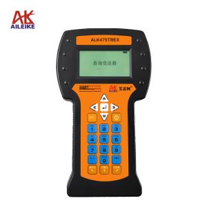
Detailed Procedures for Calibrating, Testing, and Measuring AILEIKE Pressure Switches
Pressure switches are core components of industrial pressure control systems; the accuracy of their actuation and reset values determines the stability of equipment operation, making regular calibration, testing, and measurement particularly critical. To standardize operational procedures and ensure equipment performance meets specifications, these procedures outline the calibration of pressure switches using the ALKT511 micro-pressure calibration bench and the ALKC400E digital pressure calibrator. Throughout the process, standard operating environments and procedures are strictly adhered to. Equipment wiring and parameter settings are completed, and the actuation and reset parameters of the pressure switch in both normally open and normally closed states are precisely tested and verified, with strict control over operational details such as pressure adjustment and readings. At the same time, calibration and maintenance standards for the calibration instruments are clearly defined to ensure the accuracy and reliability of calibration data, enabling calibration tasks to be completed in a standardized and efficient manner and ensuring the stable operation of industrial systems.
I. Tools for Calibrating Pressure Switches
|
Name |
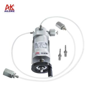
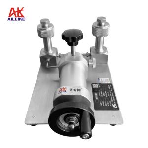
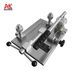
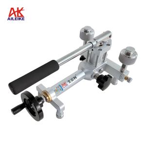
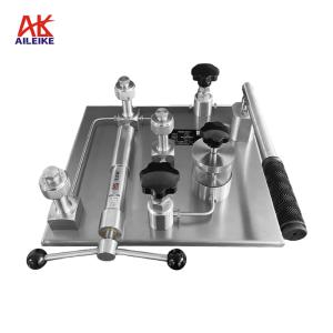
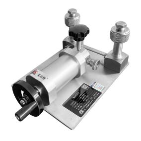
Low-Pressure Calibration Stand |
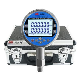
Digital Pressure Calibrator |
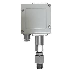
Pressure Switches |
|
Model |
ALKT511 |
ALKC400E |
Various Models |
|
Technical Specifications |
Pressurization Method: Manual Pressure: 0–600 kPa Medium: Clean air Outlets: 2 Connection: M20×1.5 (F) Net Weight: 4.6 kg Product Dimensions: 320×190×140 mm
|
Pressure: 0–600 kPa Accuracy: 0.02% FS Temperature Compensation: With temperature compensation Current Measurement: ±30.0000 mA Voltage Measurement: ±30.0000 V DC Output: 24 VDC Communication Interface: RS-232/RS-485 Power Supply: Built-in rechargeable battery Connection: M20×1.5(M) Net Weight: 0.6 kg Dimensions: 110×50×185 mm
|
Pressure Switch: 0–600 kPa Setpoint: 250 kPa Contact Type: Normally Open/Normally Closed Switching Wetted Materials: Stainless Steel Mounting Thread: M20×1.5 (default)
|
|
Product Dimensions |
|
|
|
The entire verification process must strictly comply with current metrological technical specifications. The primary references include: JJG 544-2011 “Pressure Controllers,” which applies to the initial verification, periodic verification, and in-service inspections of pressure, vacuum, and pressure-vacuum controllers (including mechanical and electronic types). These pressure control devices operate without an external power source and rely on pressure changes to directly drive mechanical components that open and close contacts.
II. Detailed Operating Procedures
(1) Preliminary Preparations
1. Environmental Requirements
Temperature should be maintained at (20±2)°C, relative humidity ≤85% RH, with no condensation. Ensure the site is free of vibration, dust, and corrosive gases.
2. Connecting Equipment
• Securely connect the pressure switch and the ALKC400E digital pressure calibrator to the outlet of the ALKT511. Press the “Electrical Measurement” button on the ALKC400E to switch to pressure switch measurement mode.
• Pressure Switch Presetting: Open the protective cover of the adjustment knob on top of the pressure switch. Prepare the adjustment tool, allowing sufficient travel for clockwise (increase) and counterclockwise (decrease) rotation, and set the pressure switch setpoint.
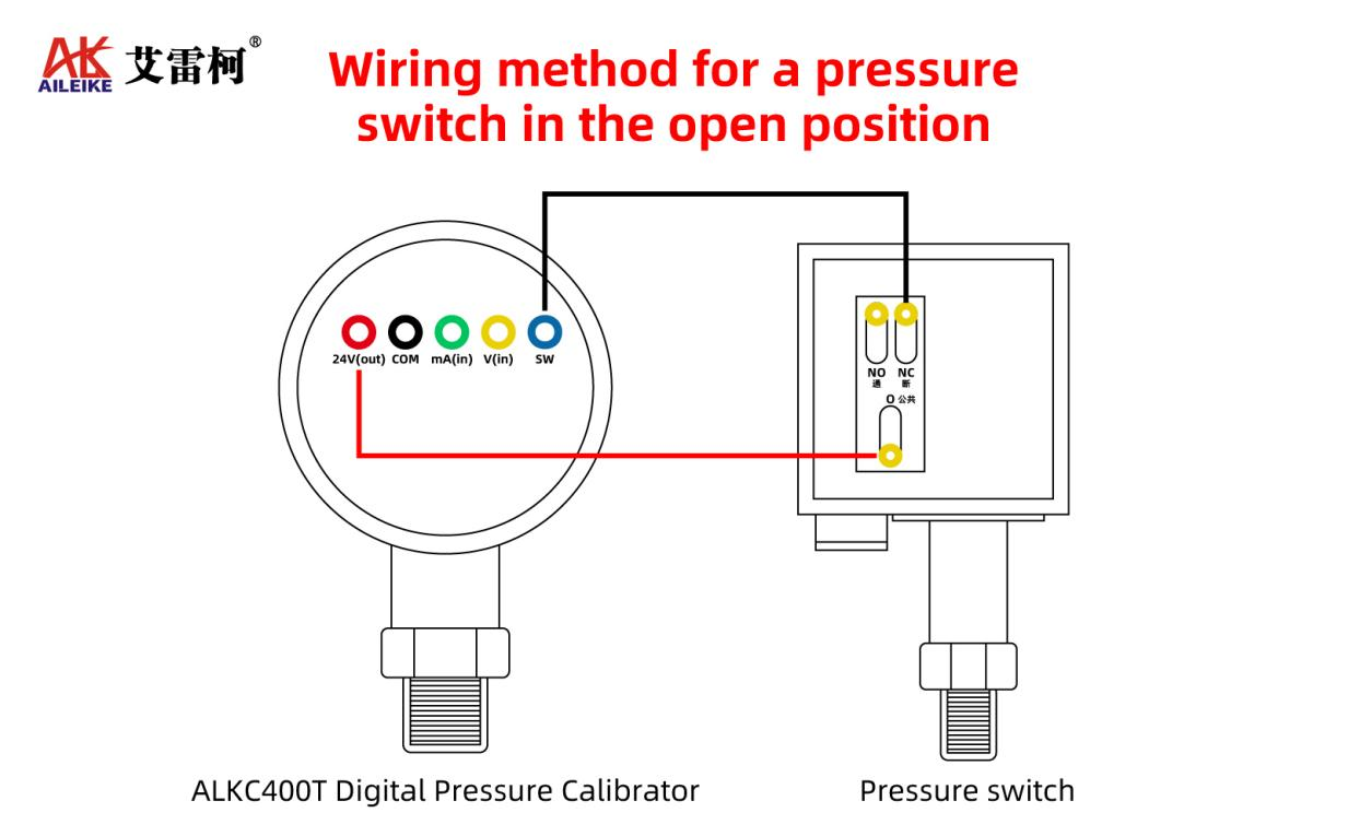
• Wiring Instructions:
(1) Connect the red test lead of the ALKC400E to the 24V output terminal of the standard meter, and the black test lead to the measurement terminal of the pressure switch.
(2) Clip the red alligator clip to the common terminal (COM) of the pressure switch, and the black alligator clip to the normally open (NC) or normally closed (NO) terminal.
(3) Now, first clip the black alligator clip to the normally open (NC) terminal. At this point, the ALKC400E pressure switch display will show the “-/-” symbol, confirming that the pressure switch is in the normal open (disconnected) state and that the wiring is correct.
(2) Operating Procedure
Core Calibration Steps: Set the target pressure to 250 kPa. Gently turn the pressure switch adjustment knob (clockwise to increase pressure, counterclockwise to decrease pressure) while applying pressure using the calibration bench to fine-tune the pressure switch’s actuation point precisely to the target pressure of 250 kPa. Once calibration is complete, lock the knob in position.
1. Closing and Opening Verification Process for the Pressure Switch in Normally Open Mode
• First, open the ALKT511 pressure-regulating valve, turn the fine-tuning knob counterclockwise until it stops, and close the relief valve.
• Use the fine-tuning knob to increase pressure clockwise until the upper threshold (actuation pressure) of 250 kPa is reached. You will hear a “beep” from the instrument, the contact status will change, and the display on the standard gauge will change from “-/-” to “--.” The pressure switch will switch from the open state to the closed state; record the actuation pressure value.
• Continue using the fine-tuning knob to reduce the pressure counterclockwise until it reaches the lower threshold (reset value) of 240 kPa. You will again hear a “beep” from the instrument, the contact status will change, the display on the standard gauge will change back from “--” to “-/-”, and the pressure switch will switch from the closed state to the open state. Record the reset pressure value.
• Once the test is complete, open the relief valve to gradually release the pressure in the pipeline. When the pressure reaches 0, the measurement is complete.
2. Test Procedure for Closing and Opening the Pressure Switch in a Normally Closed State
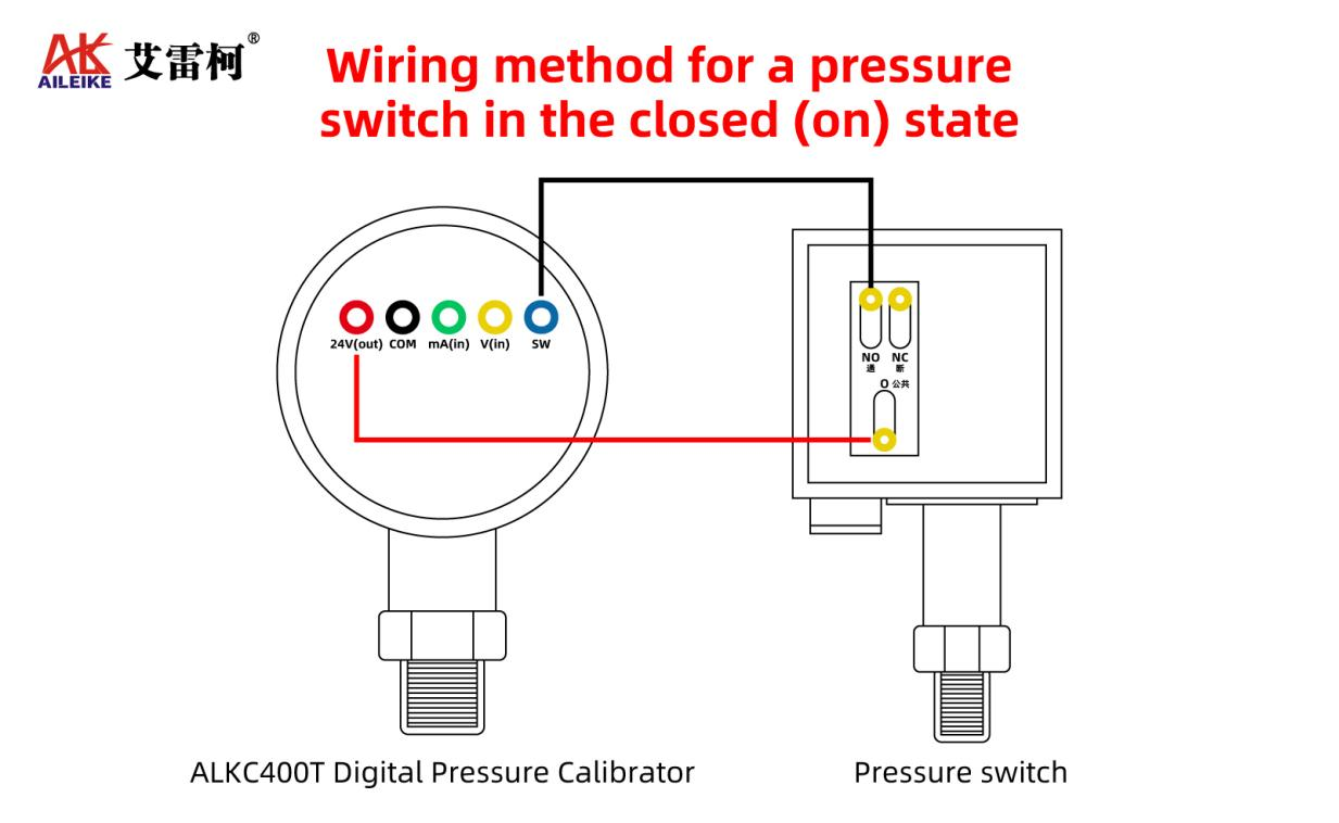
• First, clip the black alligator clip to the normally open (NO) terminal. You will then see that the pressure switch is in the normally open state, and the standard gauge pressure switch displays the “--” closed symbol.
• Turn the fine-tuning knob counterclockwise until it stops, then close the relief valve.
• Use the fine-tuning knob to increase pressure clockwise until it reaches the upper threshold (actuation value) of 250 kPa. You will hear a “beep” from the instrument, the contact status will change, the standard gauge display will switch from “--” to “-/-”, and the pressure switch will switch from the closed state to the open state. Record the actuation pressure value.
• Continue using the fine-tuning knob to reduce the pressure counterclockwise until it reaches the lower cut-off value (reset value) of 240 kPa. You will again hear a “beep” from the instrument, the contact status will change, the display on the standard gauge will change from “-/-” to “--”, and the pressure switch will return from the open state to the closed state. Record the reset pressure value.
• Once the test is complete, open the pressure relief valve to gradually release the pressure in the pipeline. When the pressure is fully relieved to 0, the measurement is complete.
III. Precautions
Proper Use
• Follow standard operating procedures. Pressurization and depressurization of the ALKT511 low-pressure calibration stand must be performed slowly to avoid pressure surges.
• Ensure correct wiring of the ALKC400E digital pressure calibrator; strictly prevent reverse connections.
• Readings at calibration points must be taken only after the standard gauge reading has stabilized to ensure real-time accuracy.
• At the end of the test, slowly relieve the pressure to zero and ensure there is no residual pressure before removing the instrument under test.
Maintenance and Calibration Schedule
• Perform periodic metrological verification on the ALKC400E digital pressure calibrator (recommended once a year) to ensure measurement accuracy meets standards.
• Turn off the power when the pressure gauge is not in use; if not used for an extended period, recharge it once every three months.
• If the low-pressure test bench is not in use for an extended period, depressurize it before storage and cover it with a cloth cover to prevent dust from entering the instrument.
IV. Conclusion
Through systematic measurement, testing, and calibration procedures, this project completed a full-condition performance verification of the pressure switches. It precisely calibrated and validated two core parameters—the actuation value and the reset value—and verified the contact operation performance of the equipment under both normally open and normally closed conditions. Throughout the entire process, key steps—such as pressure regulation, circuit connections, and data acquisition—were managed under standardized controls, effectively minimizing human error and ensuring the authenticity and accuracy of all measurement data. Relying on standardized instrument calibration and maintenance mechanisms, the accuracy of calibration work is continuously ensured. Regular calibration and testing of pressure switches can effectively identify potential performance deviations, correct parameter discrepancies, and enhance equipment control precision and operational reliability, thereby providing a solid technical foundation for the stable and efficient operation of industrial pressure control systems.
Related News