

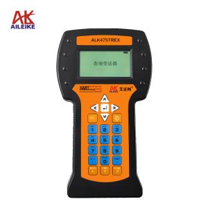
Operating Procedures for Error Verification and Calibration of HART Protocol Pressure Transmitters
To ensure the accuracy of pressure data acquisition under industrial production conditions, HART protocol pressure transmitters must undergo periodic metrological calibration. These operating procedures use the ALKY15A box-type pressure calibrator (with temperature compensation) and the ALK475TREX Chinese-language HART handheld communicator as the core reference instruments, and the entire testing process is conducted in a standard calibration environment characterized by constant temperature and humidity, free from vibration and corrosive gases. The process includes environmental stabilization and pre-treatment, connection of the instrument’s power supply circuit and pressure lines, zero-point calibration of the instrument, as well as bidirectional, point-by-point testing involving pressure increases and decreases across the full range. It involves a precise comparison of the correspondence between the standard pressure input and the 4–20 mA output and HART digital signals, and targeted adjustment of zero-point and span offset errors. Pressure is controlled at a constant rate throughout the entire operation, and readings are recorded only after the display stabilizes. This ensures the authenticity and validity of measurement data, as well as compliance with traceability requirements, thereby providing metrological assurance for the stable operation of the plant-wide pressure control system.
I. Tools for Calibrating Pressure Transmitters (HART Protocol)
|
Name |
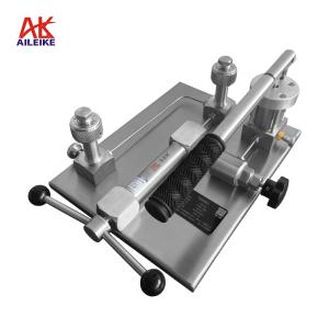
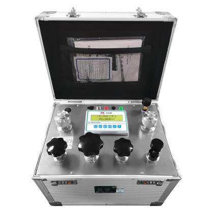
Chamber-Type Pressure Calibrator |
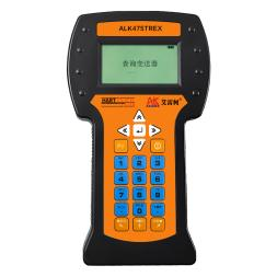
HART Handheld Programmer |
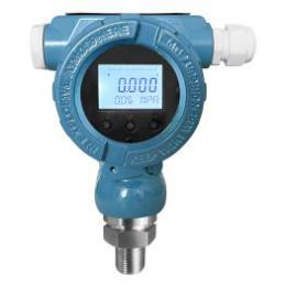
Pressure Transmitters |
|
Model |
ALKY15A (with Temperature Compensation) |
ALK475TREX (Chinese Version) |
Various Models |
|
Technical Specifications |
Pressurization Method: Manual Pressure: -0.095 to 2.5 MPa Medium: Clean air Outlets: 2 Connection: M20×1.5(F) Accuracy: Pressure: 0.05% F.S. Current: 0.05% ± 1d Display: 4½-digit LCD, 5½-digit LCD (dual display for pressure and current) DC Operating Time: ≥16 h Current Measurement: 0–22 mA DC Voltage Output: 24 VDC Overload Capacity: 1.2 times full scale Power Supply: 220 VAC, 50 Hz, 3 VA Weight: 6.5 kg Dimensions: 365 × 228 × 320 mm
|
Communication: HART Protocol Display: Black-and-white screen Language: Chinese DC Output: 24V DC Power Supply: Built-in rechargeable battery Net Weight: 0.5 kg Dimensions: 230 × 130 × 45 mm
|
Pressure: -0.1 to 2.5 MPa Accuracy: ±0.1% FS ±0.2% FS ±0.5% FS Output Signal: 4 to 20 mA + HART Power Supply: 24 VDC Connection: M20×1.5 (M)
|
|
Product Design
|
|
|
|
The entire verification process must strictly comply with current metrological technical specifications. The primary references include: JJG 882-2019 “Pressure Transmitters,” which applies to the verification, periodic calibration, and in-service inspection of pressure transmitters, and is used to standardize the measurement error, hysteresis, and repeatability of transmitters.
II. Detailed Explanation of the Operational Process
(1) Preliminary Preparations
1. Environmental Requirements
The temperature must be maintained at (20±2) °C, with relative humidity ≤ 85% RH and no condensation. The site must be free from vibration, dust and corrosive gases.
2. Connecting the Equipment
• Securely connect the pressure transmitter (HART protocol) to the output port of the ALKY15A box-type pressure calibrator (with temperature compensation). Secure any unused output ports with plugs, then turn on the power switch.
• Wiring Method 1 (24V Power Supply from the Enclosed Pressure Calibrator):
(1) Red test lead connection: Insert one end into the calibrator’s 24V port, and clip the other end to the transmitter’s positive terminal.
(2) Connect the transmitter’s negative terminal to a 250Ω resistor.
(3) Black test lead connection: Insert one end into the calibrator’s current port, and clip the other end to one side of the 250Ω resistor.
(4) Handheld communicator communication cable connection: Plug one end into the handheld communicator’s communication port, and clip the other end to both ends of the 250Ω resistor
(5) Once the connections are complete, a closed loop is formed
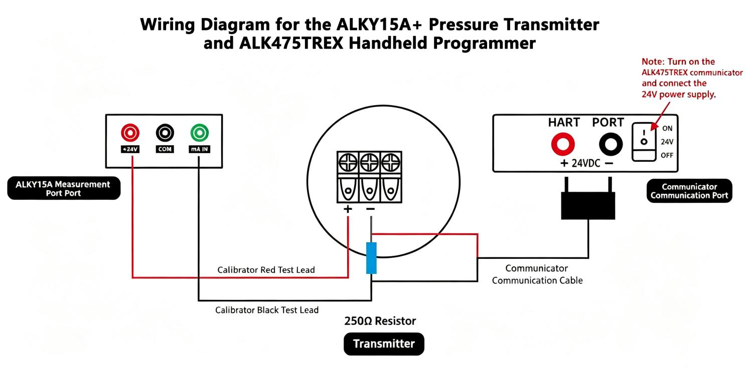
Wiring Diagram (1)
• Wiring Method 2 (ALK475TREX Handheld Unit with 24V Power Supply):
(1) Red test lead connection: Insert one end into the calibrator’s current port, and clip the other end to the transmitter’s negative terminal.
(2) Black test lead connection: Insert one end into the calibrator’s common port.
(3) Handheld unit communication cable connection: Plug one end into the handheld unit’s communication port; clip the red clamp to the transmitter’s positive terminal, and clip the black clamp together with the clamp on the calibrator’s black test lead
(4) Once the connections are complete and a closed loop is formed, turn on the ALK475TREX handheld unit’s 24V switching power supply
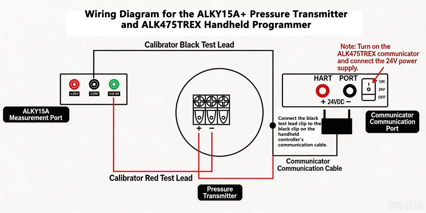
Wiring Diagram (2)
• If the transmitter does not display 0 at the current atmospheric pressure, and the calibrator detects a deviation in the transmitter’s 4 mA current value, use a HART handheld communicator to calibrate the transmitter’s zero point and current.
3. Specific Calibration Steps Using the Handheld Communicator
(1) Calibrating the Transmitter’s Zero Point
Turn on the handheld communicator. The handheld communicator has successfully established communication with the pressure transmitter.
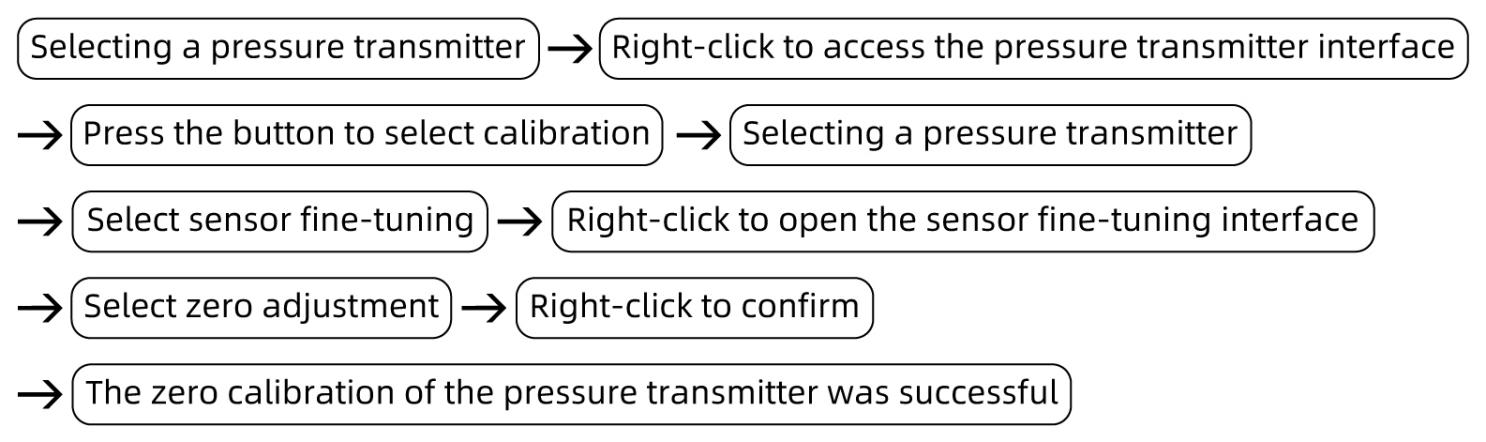
(2) The transmitter current value measured by the box-type pressure calibrator is 4 mA or 20 mA
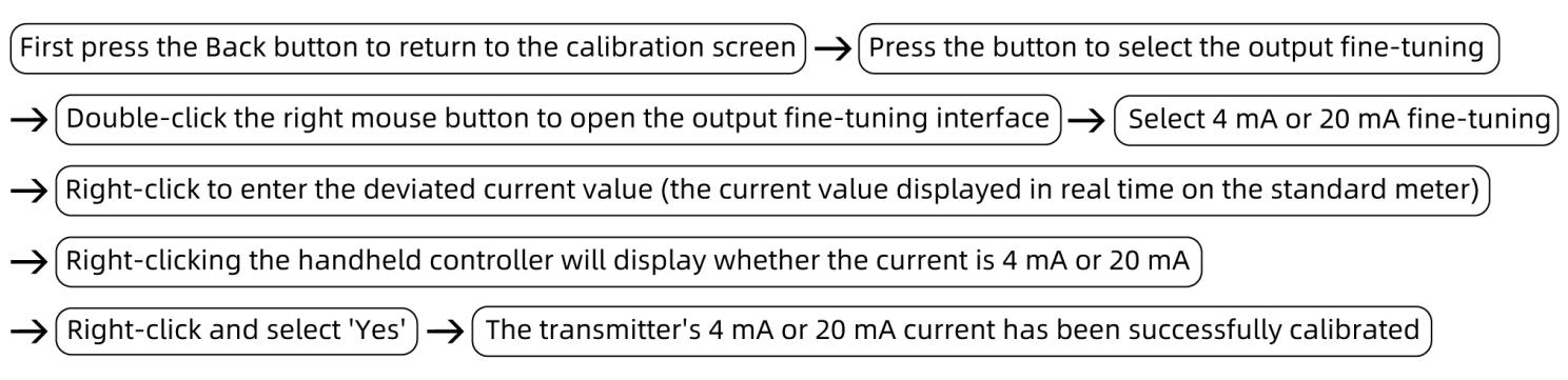
(2) Positive Pressure Calibration Process for Pressure Transmitters (HART Protocol)
1. Pressure Increase Calibration Process
• First, press down on the ALKY15A positive/negative pressure medium switching valve (do not switch while under pressure), then turn the fine-adjustment valve counterclockwise to the appropriate position, and finally close the pressure relief valve.
• Next, use a hand pump to pressurize the system. Stop when the pressure reaches approximately the target calibration value, then use the fine-tuning valve to adjust the pressure to the calibration value of 0.5 MPa. If there is a deviation between the pressure value measured by the transmitter and 0.5 MPa, or if the current value of 7.2 mA measured by the calibrator also deviates, use the handheld calibrator to calibrate both the pressure and current values.
• Calibrating the Transmitter’s Pressure Reading:
Select either “Low Range Fine-Tuning” or “High Range Fine-Tuning.” If the transmitter’s measured pressure is below 0.5 MPa, select “Low Range Fine-Tuning”; if it is above 0.5 MPa, select “High Range Fine-Tuning.” Then press the right button, enter the pressure value of 0.5 MPa, and finally press the right button again to confirm. Both the pressure and current values will be successfully calibrated.
• Follow the same procedure, using a hand-operated pump to pressurize the system. Stop when the pressure reaches approximately the target calibration value, then use the fine-tuning valve to adjust to the calibration pressures of 1 MPa, 1.5 MPa, 2 MPa, and 2.5 MPa. The corresponding current values should be 10.4 mA, 13.6 mA, 16.8 mA, and 20 mA, respectively. If there are any deviations, calibrate using the handheld calibrator (following the same procedure as above).
2. Decompression Calibration Process
• Open the relief valve to reduce pressure, stopping when the pressure is approximately at the target calibration value. Then use the fine-tuning valve to adjust to the calibration pressure of 2 MPa. If the pressure value measured by the transmitter deviates from 2 MPa, or if the current value of 16.8 mA measured by the calibrator for the pressure transmitter also deviates, use the handheld calibrator to calibrate both the pressure and current values.
• Repeat the same procedure: open the relief valve to reduce pressure, stop when the pressure is approximately at the target calibration value, and then use the fine-tuning valve to adjust the pressure to the calibration values of 1.5 MPa, 1 MPa, and 0.5 MPa. The corresponding current values should be 13.6 mA, 10.4 mA, and 7.2 mA, respectively. If there are errors, calibrate them using the handheld calibrator (follow the same procedure as above).
• Record the correspondence between pressure and current at each point, and verify that the hysteresis (the current difference at the same point during pressure increase and decrease) meets the requirement (≤0.05% FS).
3. Pressure Relief Process
Open the relief valve to gradually release the pressure in the pipeline. When the pressure reaches 0, the measurement is complete.
(3) Negative Pressure Calibration Process for Pressure Transmitters (HART Protocol)
1. Pressure Increase Calibration Process
• Lift the medium switching valve upward (do not switch under pressure), then turn the fine-adjustment valve clockwise to the appropriate position, and finally close the pressure relief valve.
• Next, use a hand pump to pressurize the system until the pressure reaches approximately the target calibration value, then stop. Use the fine-tuning valve to adjust the pressure to the calibration vacuum value of -0.02 MPa. If there is a deviation between the pressure value measured by the transmitter and -0.02 MPa, or if the current value of 16.6 mA measured by the calibrator also deviates, use the handheld calibrator to calibrate both the pressure and current values.
• Calibrating the transmitter’s pressure reading:
Select either “Low Range Fine-Tuning” or “High Range Fine-Tuning.” If the pressure value measured by the transmitter is below -0.02 MPa, select “Low Range Fine-Tuning”; if the pressure value is above -0.02 MPa, select “High Range Fine-Tuning.” Then press the right button, enter the pressure value of -0.02 MPa, and finally press the right button again to confirm. Both the pressure value and current value will be successfully calibrated.
• Follow the same procedure, using a hand-operated pressure pump to pressurize the system. Stop when the pressure reaches approximately the target calibration value, then use the fine-tuning valve to adjust the pressure to -0.04 MPa, -0.06 MPa, -0.08 MPa, and -0.095 MPa. the corresponding current values should be 13.2 mA, 9.8 mA, 6.5 mA, and 4 mA, respectively. If there is an error, calibrate using the handheld calibrator (follow the same procedure as above).
2. Depressurization Calibration Process
• Open the relief valve to reduce pressure. Stop when the pressure is approximately at the target calibration value, then use the fine-tuning valve to adjust to the calibration pressure value of -0.08 MPa. If there is a deviation between the pressure value measured by the transmitter and -0.08 MPa, or if there is a deviation in the current value (6.5 mA) measured by the calibrator for the pressure transmitter, use the handheld calibrator to calibrate both the pressure and current values.
• Repeat the same procedure: open the relief valve to reduce pressure, stop when the pressure is approximately at the target calibration value, and then use the fine-tuning valve to adjust the pressure to the calibration values of -0.06 MPa, -0.04 MPa, and -0.02 MPa. The corresponding current values should be 9.8 mA, 13.2 mA, and 16.6 mA, respectively. If there are any deviations, calibrate them using the handheld calibrator (following the same procedure as above).
• Record the correspondence between pressure and current at each point, and verify that the hysteresis (the current difference at the same point during pressure increase and decrease) meets the requirement (≤0.05% FS).
3. Pressure Relief Process
Open the pressure relief valve to gradually release the pressure in the pipeline. When the pressure reaches 0, the measurement is complete.
III. Precautions
Proper Use
• Follow standard operating procedures. When pressurizing or depressurizing the ALKY15A cabinet-type pressure calibrator (with temperature compensation), proceed slowly to avoid pressure surges.
• Do not switch between positive and negative pressure measurements while the system is under pressure.
• Ensure the communication cable connecting the ALKY15A Enclosed Pressure Calibrator to the handheld controller is correctly wired; take strict precautions against reverse connections.
• Read and record measurements at calibration points only after the values on the ALKY15A Enclosed Pressure Calibrator have stabilized to ensure real-time accuracy.
• Without the appropriate technical skills and testing equipment, do not open the instrument’s cover for maintenance, and under no circumstances adjust or replace components; otherwise, the accuracy of the instrument’s measurements cannot be guaranteed.
• Upon completion of the test, slowly depressurize the unit to zero and ensure there is no residual pressure. Turn off the power before removing the instrument under test.
Maintenance and Calibration Schedule
• Perform periodic metrological verification on the ALKY15A box-type pressure calibrator (with temperature compensation) (recommended once a year) to ensure measurement accuracy meets standards.
• When the calibrator is not in use, turn off the power. If it will be out of use for an extended period, recharge the battery once every three months.
• If the ALKY15A Enclosed Pressure Calibrator (with Temperature Compensation) will not be used for an extended period, depressurize it before storage and cover it with a cloth cover to prevent dust from entering the instrument.
IV. Conclusion
Implementing standardized verification and testing of HART pressure transmitters can systematically eliminate various measurement deviations caused by long-term instrument operation, ensuring that full-range pressure and current outputs meet metrological control standards. During operations, focus on key steps such as circuit verification, uniform pressure adjustment, stable pressure readings, and bidirectional verification to reduce human operational errors and extend the instrument’s service life. Organize regular standardized verification to maintain a consistently stable level of instrument metrology, thereby providing reliable assurance for pressure monitoring at production sites.
Related News