

Measurement, Verification and Calibration Procedures for Industrial Differential Pressure Transmitters
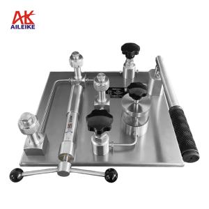
Differential pressure transmitters are core sensing devices in industrial automation and process control, and regular standardised verification and calibration are of particular importance. In this test, the ALKT512 low-pressure calibration bench, the ALKC400T precision digital pressure gauge and the ALK475TREX handheld programmer were utilised to conduct stepwise positive and negative pressure increase/decrease tests on the differential pressure transmitter in a constant temperature and humidity environment, whilst comparing the pressure and current output in real time to verify linearity and hysteresis. Through standardised wiring, gradual pressure adjustment, precise data recording and correction of deviations, we ensured that measurement accuracy and equipment performance met the required standards, thereby providing reliable metrological assurance for precise industrial pressure measurement and control, as well as the stable operation of the system.I. Tools for Calibrating Differential Pressure Transmitters
|
Name |
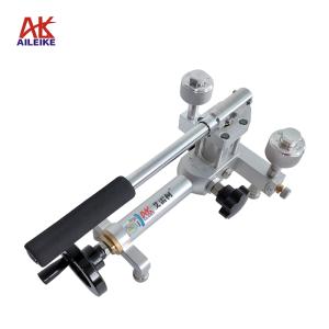
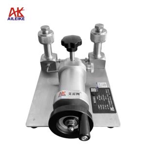
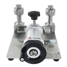
Micro-pressure calibration bench |
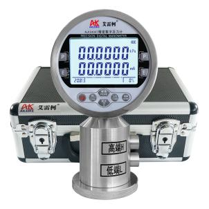
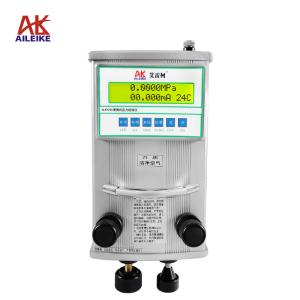
Precision Digital Pressure Gauge |
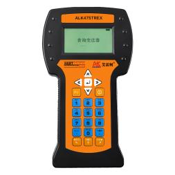
HART Handheld Terminal |
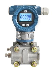
Digital Differential Pressure Transmitter |
|
Model |
ALKT512 |
ALKC400T(Differential pressure type) |
ALK475TREX(Chinese version) |
ALK3051DP |
|
Technical Specifications |
Pressurisation method: Manual Pressure: ±6000 Pa Medium: Clean air Outlets: 2 Connection: M20×1.5(F) Net weight: 4.9 kg Product dimensions: 320×190×140 mm
|
Pressure: ±6000 Pa Accuracy: 0.05% FS Temperature compensation: With temperature compensation Current measurement: ±30.0000 mA Voltage measurement: ±30.0000 V DC output: 24 V DC Communication Interface: RS-232/RS-485 Power Supply: Built-in rechargeable battery Connection: M10×1 Net Weight: 0.85 kg Dimensions: 110×75×190 mm
|
Accuracy class: ±0.05% FS Communication: HART protocol Display: Monochrome screen Language: Chinese DC output: 24 V DC Power supply: Built-in rechargeable battery Net weight: 0.5 kg Dimensions: 230 × 130 × 45 mm
|
Pressure: ±6000 Pa Accuracy: ±0.2% FS Output signal: 4–20 mA Power supply: 24 V DC Net weight: 3.5 kg |
|
Product Dimensions |
|
|
|
|
The entire verification process must be carried out in strict accordance with current metrological technical specifications. The main references include:JJG 882-2019 ‘Pressure Transmitters’, which applies to the verification, periodic calibration and in-service inspection of pressure transmitters, and is used to standardise the indication error, hysteresis and repeatability of transmitters.
II. Detailed Explanation of the Operational Process
(1) Preliminary Preparations
1. Environmental Requirements
The temperature must be maintained at (20±2) °C, with relative humidity ≤ 85% RH and no condensation. Ensure that the site is free from vibration, dust and corrosive gases.
2. Connection of Equipment
• Connect the ALK3051DP differential pressure transmitter and the ALKC400T precision digital pressure gauge (differential pressure type, hereinafter referred to as the differential pressure gauge) to the output ports of the ALKT512 low-pressure calibration bench in a sealed manner.
(1) Connect the high-range port of the differential pressure gauge to one of the output ports of the ALKT512.
(2) Connect the high-range port of the differential pressure transmitter to the other output port of the ALKT512.
• Wiring Method 1 (24 V power supply for precision digital pressure gauge):
(1) Red test lead connection: Insert one end into the 24 V socket on the standard meter; clip the other end to the positive terminal of the transmitter
(2) Connect the negative terminal of the transmitter to a 250 Ω resistor
(3) Black test lead connection: Insert one end into the current socket on the standard meter; clip the other end to one side of the 250 Ω resistor
(4) Handheld communicator communication cable connection: Insert one end into the handheld communicator’s communication port, and clip the other end to both ends of the 250 Ω resistor
(5) Once the connections are complete, a closed circuit is formed
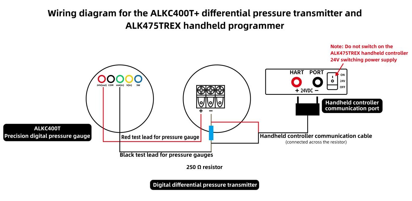
Wiring Diagram (1)
• Wiring Method 2 (ALK475TREX Handheld Transmitter, 24V Power Supply):
(1) Red test lead connection: Insert one end into the standard meter’s current socket and clip the other end to the negative terminal of the transmitter
(2) Black test lead connection: Insert one end into the standard meter’s common terminal
(3) Handheld unit communication cable connection: Insert one end into the handheld unit’s communication port; clip the red clamp to the transmitter’s positive terminal, and clip the black clamp together with the clamp on the black test lead
(4) Once the connections are complete, forming a closed circuit, switch on the ALK475TREX handheld unit’s 24V switching power supply
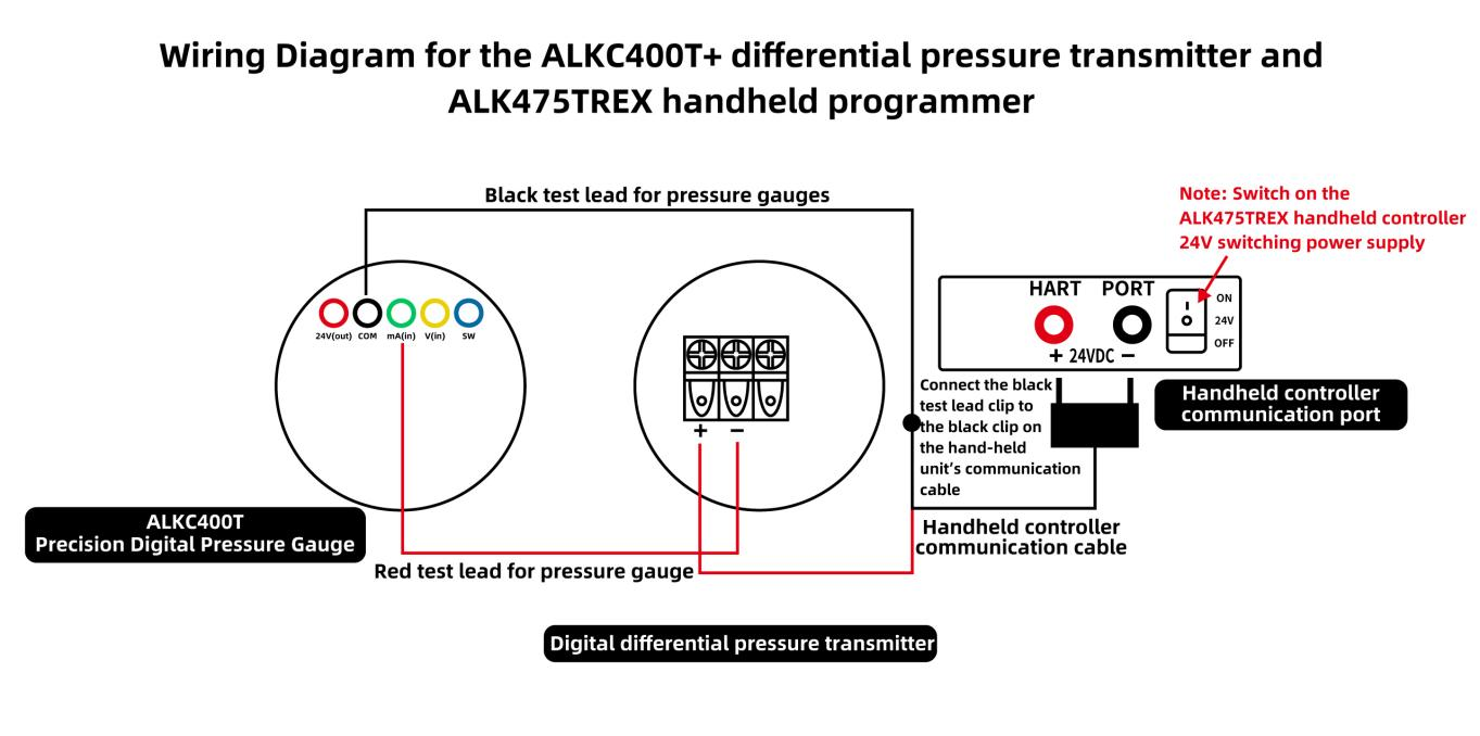
Wiring Diagram (2)
• If the differential pressure transmitter does not read zero at the current atmospheric pressure, and the standard gauge indicates that the differential pressure transmitter’s current reading of 12 mA is inaccurate, use a HART handheld communicator to calibrate the transmitter’s zero point and current.
(2) Positive Pressure Calibration Procedure for Differential Pressure Transmitters
1. Pressure Increase Calibration Procedure
• First, open the ALKT512 shut-off valve, turn the pressure adjustment knob anti-clockwise to the appropriate position, turn the fine-tuning knob anti-clockwise to the appropriate position, and then close the vent valve.
• Using the pressure adjustment handle, slowly increase the pressure by turning it clockwise until it reaches approximately the calibration value. Use the fine-tuning knob to adjust the pressure to the calibration value of 3000 Pa. If the pressure value measured by the differential pressure transmitter deviates from 3000 Pa, and the current value of 16 mA measured by the differential pressure gauge also deviates, use the handheld calibrator to calibrate the pressure and current values.
• Calibrating the transmitter’s pressure value:
Select either the low-range fine-tuning or high-range fine-tuning function. If the pressure value measured by the transmitter is below 3000 Pa, select low-range fine-tuning; if it is above 3000 Pa, select high-range fine-tuning. Then press the right button, enter the pressure value 3000 Pa, and finally press the right button again to confirm. Both the pressure value and current value will be successfully calibrated.
• Following the same procedure, use the pressure adjustment knob to slowly increase the pressure clockwise until it reaches approximately the calibration value. Use the fine-tuning function to adjust to the calibration value of 6000 Pa; the current value should be 20 mA. If there is an error, calibrate using the handheld calibrator (as described above).
2. Depressurisation Calibration Procedure
• Using the pressure adjustment knob, slowly reduce the pressure anti-clockwise until it is approximately at the calibration value. Use the fine-tuning knob to adjust to the calibration value of 3000 Pa. The current value measured by the differential pressure gauge should be 16 mA. If there is a deviation, use the handheld calibrator to calibrate the pressure and current values.
• Record the correspondence between pressure and current at each point, and verify that the hysteresis (the difference in current at the same point during pressure increase and decrease) meets the requirement (≤0.05% FS).
3. Depressurisation Procedure
Open the vent valve and gradually release the pressure within the pipeline. Once the pressure has been reduced to 0, the measurement is complete.
(3) Negative Pressure Calibration Procedure for Differential Pressure Transmitters
1. Pressure Increase Calibration Procedure
• With the ALKT512 shut-off valve in the open position, turn the pressure adjustment knob clockwise to the appropriate position, turn the fine-tuning knob clockwise to the appropriate position, and then close the vent valve.
• Use the pressure adjustment handle to slowly create a vacuum by turning it anti-clockwise until the pressure reaches approximately the calibration value; then use the fine-tuning knob to adjust it to the calibration value minus 3000 Pa. If the pressure value measured by the differential pressure transmitter deviates from –3000 Pa, and the differential pressure gauge indicates that the transmitter’s current value of 8 mA also deviates, use the handheld calibrator to calibrate the pressure and current values.
• Calibrating the transmitter’s pressure reading:
Select either the low-range fine-tuning or high-range fine-tuning. If the pressure reading measured by the transmitter is below –3000 Pa, select low-range fine-tuning; if the pressure reading is above –3000 Pa, select high-range fine-tuning. Then press the right button, enter the pressure value –3000 Pa, and finally press the right button again to confirm. Both the pressure and current readings will be successfully calibrated.
• Following the same procedure, use the pressure adjustment knob to slowly evacuate the system clockwise until the pressure reaches approximately the calibration value. Use the fine-tuning function to adjust to the calibration value of –6000 Pa; the current value should be 4 mA. If there is an error, calibrate using the handheld controller (as described above).
2. Decompression calibration procedure
• Use the pressure adjustment knob to slowly reduce the pressure clockwise until it reaches approximately the calibration value. Use the fine-tuning knob to adjust to the calibration value minus 3,000 Pa. The current value measured by the differential pressure gauge should be 8 mA. If there is a deviation, use the handheld calibrator to calibrate the pressure and current values.
• Record the correspondence between pressure and current at each point, and verify that the hysteresis (the difference in current at the same point during both pressure increase and decrease) meets the requirement (≤0.05% FS).
3. Depressurisation Procedure
Open the vent valve and gradually release the pressure within the pipeline. Once the pressure has been reduced to 0, the measurement is complete.
III. Precautions
Proper Use
• Operations must be carried out in accordance with standard procedures. When pressurising or depressurising the ALKT512 precision pressure calibration bench, do so slowly to avoid pressure surges.
• Ensure the communication cable connecting the differential pressure gauge to the handheld controller is correctly connected; take great care to avoid reverse connections.
• Readings at the calibration point must be taken only after the value on the standard gauge has stabilised, and must be recorded accurately and in real time.
• Upon completion of the test, first slowly depressurise the system to zero, ensuring there is no residual pressure, then switch off the power supply before removing the instrument under test.
Maintenance and Calibration Intervals
• The ALKC400T precision digital pressure gauge (differential pressure type) must undergo periodic metrological verification (recommended once a year) to ensure measurement accuracy meets standards.
• When the pressure gauge is not in use, the power supply should be switched off; if not used for an extended period, it should be recharged once every three months.
• When the precision pressure calibration bench is not in use for an extended period, it must be depressurised before storage and covered with a cloth cover to prevent dust from entering the instrument.
IV. Conclusion
This differential pressure transmitter calibration strictly adhered to standardised metrological procedures, involving stepwise pressure ramp-up and ramp-down tests across the full positive and negative pressure ranges. Using AILEIKE calibration equipment, pressure readings and 4–20 mA current output parameters were precisely calibrated to verify the instrument’s linearity and hysteresis performance, effectively correcting measurement deviations and ensuring that all error parameters comply with industry technical specifications. This calibration met the practical requirements of industrial measurement and control, precisely calibrating the instrument’s core operating parameters and enhancing the accuracy and stability of data acquisition and signal transmission for the differential pressure transmitter. Regular, standardised calibration procedures can effectively prevent process control deviations caused by instrument inaccuracies, thereby ensuring the precise, long-term and stable operation of industrial automation control systems.
Related News