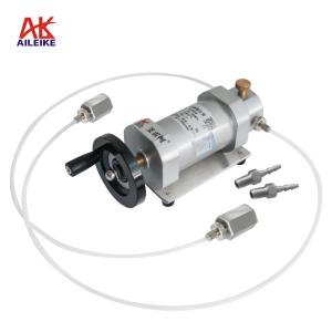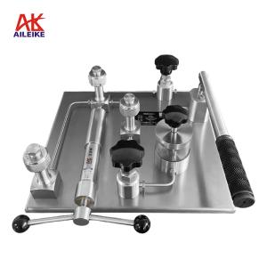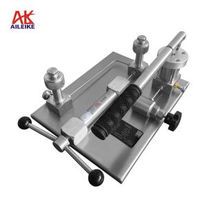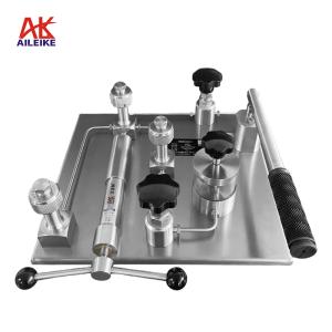



Enclosed Electric-Hydraulic Calibration Stand: A Comprehensive Operational Guide for the Entire Process of Pressure Transmitter Verification and Calibration
Pressure transmitters (HART protocol) are core measuring instruments in industrial process measurement; their measurement accuracy directly affects the precision of production control, equipment operation, and data accuracy. Conducting regular calibration and testing is an essential step in ensuring instrument performance. This calibration utilized the ALKD102B box-type electro-hydraulic calibration bench and the ALK475TREX HART handheld communicator (Chinese version). Through standard pressure comparison, current signal testing, and HART communication calibration, a comprehensive measurement verification was conducted on the transmitter’s zero point, span, and pressure readings and current output at each calibration point, covering the entire process from pressurization to depressurization. Operations strictly followed standardized procedures, precisely correcting indication deviations to ensure the instrument’s metrological performance met the required standards.
I. Tools for Calibrating Pressure Transmitters (HART Protocol)
|
Name |
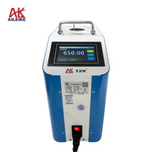
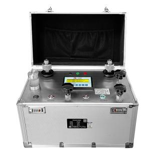
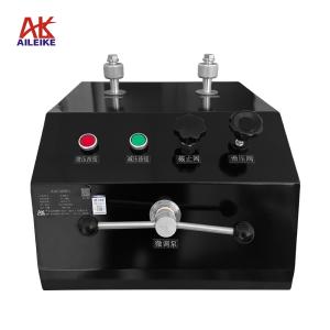
Enclosed Electric-Hydraulic Calibration Stand |
HART Handheld Programmer |
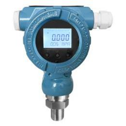
Pressure Transmitters |
|
Model |
ALKD102B |
ALK475TREX (Chinese Version) |
Various Models |
|
Technical Specifications |
Pressure Range: 0–60 MPa Medium: Calibration oil Output Ports: 2 Connection: M20×1.5(F) Accuracy: Pressure: 0.05% F.S. Current: 0.05% F.S. Resolution: Pressure: 10 Pa Current: 1 μA Current Measurement Range: 0–22 mA DC Output: 24 VDC Display: Simultaneous LCD display of pressure and current Supply Voltage: AC 220 V Weight: 12 kg Dimensions: 360 × 260 × 390 mm
|
Communication: HART Protocol Display: Black-and-white screen Language: Chinese DC Output: 24V DC Power Supply: Built-in rechargeable battery Net Weight: 0.5 kg Dimensions: 230 × 130 × 45 mm
|
Pressure: 0–60 MPa Accuracy: ±0.1% FS ±0.2% FS ±0.5% FS Output Signal: 4–20 mA + HART Power Supply: 24 VDC Connection: M20×1.5(M)
|
|
Product Dimensions |
|
|
|
The entire verification process must strictly comply with current metrological technical specifications. The primary references include: JJG 882-2019 “Pressure Transmitters,” which applies to the verification, periodic calibration, and in-service inspection of pressure transmitters, and is used to standardize the measurement error, hysteresis, and repeatability of transmitters.
II. Detailed Explanation of the Operational Process
(1) Preliminary Preparations
1. Environmental Requirements
The temperature must be maintained at (20±2) °C, with relative humidity ≤ 85% RH and no condensation. The site must be free from vibration, dust and corrosive gases.
2. Filling the Enclosed Electric-Hydraulic Calibration Stand
• Prepare the pressure-transmitting medium (calibration oil).
• Unscrew the cap from the reservoir and pour the medium into the reservoir until it is sufficiently filled. After filling, replace the cap on the reservoir.
3. Connecting Tools
• Connect the pressure transmitter (HART protocol) to one of the output ports on the ALKD102B Enclosed Electric-Hydraulic Calibration Stand using a sealed connection; secure the other output port with a plug. Connect the calibration stand to a 220V power source and turn on the power switch.
• Wiring Method 1 (24V Power Supply from the ALKD102B Electric-Hydraulic Calibration Bench):
(1) Red test lead: Insert one end into the calibration bench’s 24V port and clip the other end to the transmitter’s positive terminal.
(2) Connect the transmitter’s negative terminal to a 250Ω resistor.
(3) Black test lead: Insert one end into the calibration bench’s current port and clip the other end to one side of the 250Ω resistor.
(4) Handheld communicator communication cable connection: Plug one end into the handheld communicator’s communication port, and clip the other end to both ends of the 250Ω resistor
(5) Once the connections are complete, a closed circuit is formed
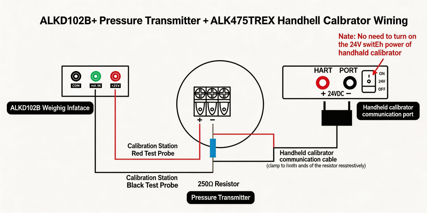
Wiring Diagram (1)
• Wiring Method 2 (ALK475TREX Handheld Unit with 24V Power Supply):
(1) Red test lead: Insert one end into the current port on the calibration bench, and clip the other end to the negative terminal of the transmitter.
(2) Black test lead: Insert one end into the common port on the calibration bench.
(3) Handheld unit communication cable connection: Plug one end into the handheld unit’s communication port; clip the red clamp to the transmitter’s positive terminal, and clip the black clamp together with the clamp on the calibration stand’s black test lead
(4) Once the connections are complete and a closed loop is formed, turn on the ALK475TREX handheld unit’s 24V switching power supply
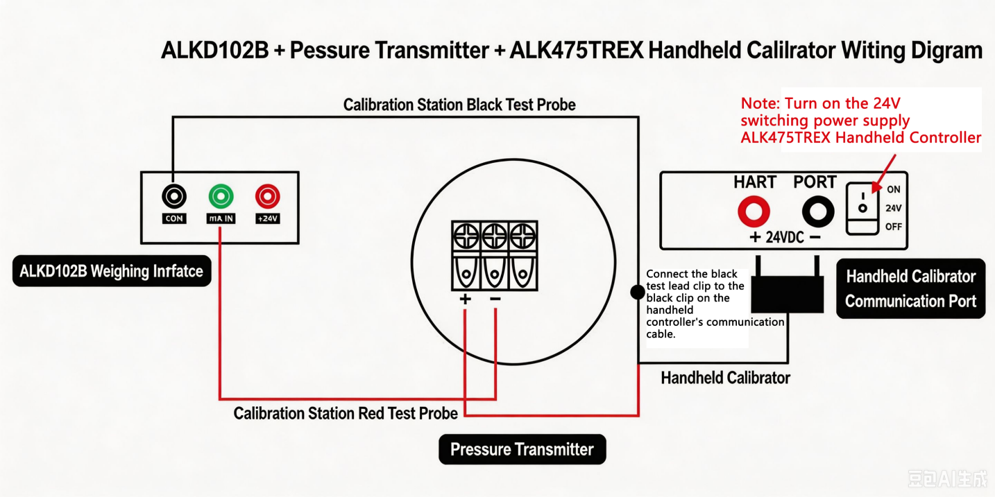
Wiring Diagram (2)
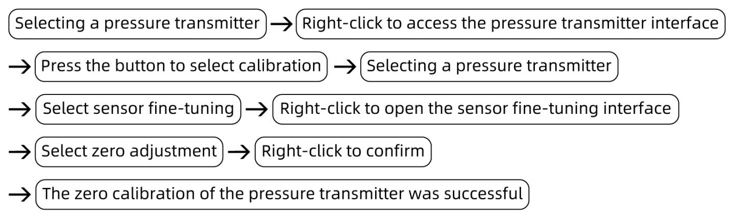
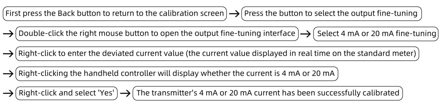
• If the transmitter does not display 0 at the current atmospheric pressure, and the calibration bench detects a deviation in the transmitter’s 4 mA current value, use a HART handheld communicator to calibrate the transmitter’s zero point and current.
4. Specific Calibration Steps Using the Handheld Communicator
(1) Calibrating the Transmitter’s Zero Point
Turn on the handheld communicator. The handheld communicator has successfully established communication with the pressure transmitter.
(2) Calibrate the 4 mA or 20 mA current value measured by the pressure gauge from the transmitter
(2) Calibration Process for Pressure Transmitters (HART Protocol)
1. Pressure-Rise Calibration Process
• First, press the pre-pressurization button on the box-type electro-hydraulic calibration bench to apply pressure. Stop when the pressure reaches approximately 1.5 MPa, then close the shut-off valve.
• Press the “Pressure Increase Fine-Tuning” button to increase the pressure; stop when the pressure reaches approximately the target calibration value. Then, use the fine-tuning valve to adjust the pressure to the calibration value of 15 MPa. If there is a deviation between the pressure value displayed on the calibration stand’s screen and the transmitter’s displayed value of 15 MPa, or if the current value measured by the calibration stand (8 mA) also shows a deviation, use the handheld communicator to calibrate the pressure and current values.
• Calibrate the transmitter’s pressure value:
Select either “Low Range Fine-Tuning” or “High Range Fine-Tuning.” If the transmitter’s measured pressure is below 15 MPa, select “Low Range Fine-Tuning”; if it is above 15 MPa, select “High Range Fine-Tuning.” Then press the right button, enter the pressure value of 15 MPa, and finally press the right button again to confirm. Both the pressure and current values will be successfully calibrated.
• Continue pressing the pressure increase fine-tuning button to increase the pressure until it stabilizes around the target value. Use the fine-tuning valve to adjust to the calibration pressure of 30 MPa. If there is a deviation between the pressure value displayed on the calibration bench and the 30 MPa displayed by the transmitter, the current value measured by the calibration bench should be 12 mA. If there is an error, calibrate using the handheld calibrator (follow the same procedure as above).
• Repeat the same procedure, increasing the pressure to 45 MPa and 60 MPa. The current values measured by the calibration stand should be 16 mA and 20 mA, respectively. If there is an error, calibrate using the handheld calibrator (follow the same procedure as above).
2. Decompression Calibration Process
• Use the pressure reduction fine-tuning valve to reduce the pressure gradually until it reaches approximately the target calibration pressure, then stop. Next, use the fine-tuning valve to adjust the pressure to the calibration value of 45 MPa. If there is a deviation between the pressure value displayed on the calibration stand and the transmitter’s reading of 45 MPa, or if the current value of 16 mA measured by the calibration stand also shows a deviation, use the handheld calibrator to calibrate both the pressure and current values.
• Repeat the same procedure to reduce the pressure to 30 MPa and 15 MPa. The current values measured by the calibration stand for the transmitter should be 12 mA and 8 mA, respectively. If there are any errors, use the handheld calibrator to correct them (follow the same procedure as above).
3. Pressure Relief Process
Continue to reduce the pressure using the fine-tuning control until the calibration bench stops operating. When the fine-tuning indicator light illuminates, open the pressure relief valve and then the shut-off valve in sequence to relieve the pressure to 0. The measurement is then complete.
III. Precautions
Proper Use
• The pressure-transmitting medium must be clean and free of impurities to prevent clogging of the piping and damage to the cabinet-type electric-hydraulic calibration bench.
• Connect the cabinet-type electric hydraulic calibration bench to a 220V power source; ensure correct connection, and do not exceed a current of 22 mA during measurement.
• Follow standard operating procedures, increasing and decreasing pressure point by point to avoid pressure surges.
• Ensure the communication cable between the calibration stand and the handheld controller, as well as the pressure transmitter wiring, are clearly identified to strictly prevent reverse connections.
• Readings at each calibration point must be taken only after the standard gauge reading has stabilized, and records must be accurate and up-to-date.
• Upon completion of the test, slowly relieve pressure to zero and ensure there is no residual pressure. Turn off the equipment’s power before removing the instrument under test.
Maintenance and Calibration Schedule
• The cabinet-type electro-hydraulic calibration bench should be installed in a temperature-controlled environment.
• If the cabinet-type electro-hydraulic calibration bench will not be used for an extended period, depressurize it before storage, drain the liquid from the reservoir, and cover it with a cloth cover to prevent dust from entering the instrument.
IV. Conclusion
This calibration of the pressure transmitter (HART protocol) involved item-by-item testing and calibration across the full range in both forward and reverse strokes. Through comparison with standard pressures, verification of current signals, and HART communication debugging, precise corrections were made to the zero point, span, and indication deviations at each calibration point, thereby validating the instrument’s metrological performance. Operating procedures were strictly followed throughout the process; readings were recorded only after values had stabilized to ensure the authenticity and traceability of the test data. The calibrated transmitter’s output signal is accurate and consistent, meeting the accuracy requirements for process measurement. Adhering to periodic calibration and routine equipment maintenance will ensure the continued reliability of pressure measurement data.
Related News