

Standardised Operating Procedures for the Calibration, Testing and Maintenance of Type K Thermocouples
Thermocouples are the core sensing elements in industrial temperature measurement systems. To ensure accurate traceability of measurement values and reliable temperature measurement performance, thermocouple calibration and testing must be carried out in accordance with relevant standards. For this calibration, the ALKW851B dry-block temperature calibration furnace was used as the constant-temperature heat source, paired with the ALKWZP-T1000 digital thermometer as the standard temperature reference. Temperature values were acquired and voltage values recorded using the ALKH513 Thermal Engineering Handbook. Environmental control, equipment connections and the multi-temperature-point heating and cooling test procedures were strictly adhered to, with the corresponding data recorded once the temperature field had stabilised. The entire operation complied with technical specifications and procedures, with regular metrological traceability checks and routine maintenance carried out to provide technical support for accurate and stable industrial temperature measurement.
I. Thermocouple Calibration Tools
|
Name |
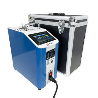
Dry-block temperature calibration oven |
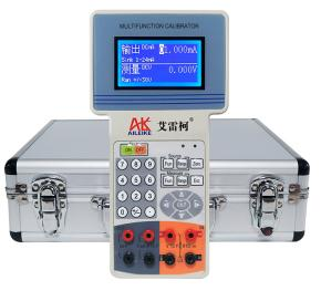
The Thermodynamics Handbook |
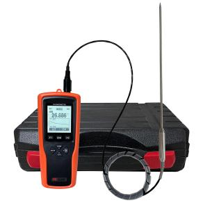
Digital thermometer |
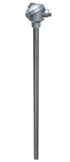
Thermocouples |
|
Model |
ALKW851B |
ALKH513 |
ALKWZP-T1000 |
Various models |
|
Technical Specifications |
Temperature range: 30–650 °C Control method: LCD touchscreen Instrument accuracy: Class 0.1 Measuring hole diameters: φ6 mm, φ8 mm, φ10 mm, φ12 mm Default display: Chinese/English switch Power supply: 220 V, 50 Hz, 600 W Weight: 12.7 kg Furnace dimensions: 360 × 165 × 330 mm
|
Signal output: DC current, DC voltage, thermocouple, thermocouple, frequency, loop-powered Accuracy: Class 0.05 Power supply: Built-in rechargeable battery Net weight: 0.7 kg Dimensions: 235 × 130 × 50 mm
|
Resolution: 0.001°C Temperature range: -200 to +800°C Calibration method: Multi-point calibration Probe length: 245 mm Probe diameter: φ4 mm Net weight: 0.25 kg Dimensions: 170 × 73 × 40 mm
|
Model: Type K Temperature measurement range: 30–650 °C Sheath material: 304 stainless steel tubing Diameter: φ12 mm Net weight: 2.4 kg Dimensions: L = 800 mm
|
|
Product Dimensions |
|
|
|
|
The entire calibration process must strictly comply with current metrological technical specifications. The primary references include: GB/T 16839.1-2018 ‘Thermocouples — Part 1: Electromotive Force Specifications and Tolerances’, which is the most fundamental general standard for Type K thermocouples and specifies the thermoelectric potential of Type K thermocouples – temperature relationship (i.e. the calibration table), tolerance classes and technical requirements. The standard mV values for all calibration scenarios are derived from this standard.
II. Detailed Explanation of the Operational Process
(1) Preliminary Preparations
1. Environmental Requirements
The temperature must be maintained at (20±2) °C, with relative humidity ≤ 85% RH and no condensation. The site must be free from vibration, dust and corrosive gases.
2. Connecting the instruments
• Place the PT probe of the ALKWZP-T1000 digital thermometer into the hole in the homogenisation block of the dry-block temperature calibration furnace. Next, set the ALKH513 Thermal Engineering Handbook to ‘Thermocouple Measurement’ mode, and then place the thermocouple probe into the hole in the homogenisation block of the dry-block temperature calibration furnace.
• When measuring the temperature of a thermocouple, select the thermocouple calibration scale on the Thermal Engineering Handbook; the screen will display the thermocouple type ‘K’, with ‘Automatic Temperature Compensation’ shown on the bottom line. ‘Automatic Compensation’ indicates automatic compensation for ambient temperature, and the corresponding mV value will also be displayed.
• Thermokind test probe wiring:
(1) Insert the red test probe into the Thermokind thermocouple measurement socket; clip the other end of the red alligator clip onto the red terminal of the thermocouple.
(2) Insert the black test probe into the Thermokind common terminal; clip both ends of the black alligator clips onto the green terminal of the thermocouple.
(3) All equipment is now successfully connected.
(2) Operating Procedures for Heating and Cooling the Dry Block Oven
1. Heating Process
• First, use high-temperature cotton wool to plug the unused holes in the heat-distribution block; the cotton wool helps to minimise heat loss and maintain a stable temperature inside the oven.
• Switch on the power supply to the temperature controller; the dry-block temperature calibration furnace will automatically enter standby mode. Next, operate the furnace’s display screen: select ‘Set Temperature’, enter the calibration value of 200 °C, then press the ‘Start’ button. Switch on the power supply to the electric furnace, and the calibration furnace will immediately begin heating automatically. When the temperature reaches 200°C, the Thermal Engineering Handbook and the digital thermometer both measure a thermocouple reading of 200°C, whilst the Thermal Engineering Handbook measures a corresponding voltage of 8.137 mV.
• Continue by pressing the ‘Set Temperature’ button and entering the temperature value 400 °C. The dry-block temperature calibration oven continues to heat up automatically. When the temperature reaches 400 °C, the Thermal Engineering Handbook and the digital thermometer both measure a thermocouple temperature of 400 °C, whilst the Thermal Engineering Handbook measures a corresponding voltage of 16.395 mV.
• Following the same procedure, enter the next temperature value of 650 °C. The dry-block temperature calibration furnace heats up automatically; when the temperature reaches 650 °C, both the Thermal Engineering Handbook and the digital thermometer measure the thermocouple temperature as 650 °C, whilst the Thermal Engineering Handbook measures the corresponding voltage as 27.015 mV.
2. Cooling Process
• First, press the ‘Stop’ button on the dry-block temperature calibration furnace screen, then switch off the power to the furnace; the dry-block temperature calibration furnace will begin to cool down naturally.
• Once the dry-block temperature calibration furnace has cooled down naturally to approximately 100 °C, switch off the power to the temperature controller; the heating and cooling cycle is now complete.
III. Precautions
Proper Use
• Do not touch the heat-distribution block or the interior of the furnace directly in the high-temperature calibration section to avoid skin burns.
• Before switching on the power, ensure that the supply voltage matches the equipment’s rated voltage to prevent electrical faults.
• The digital thermometer probe and thermocouple probe must be inserted into the holes in the heat-distribution block to ensure full contact with it.
• Ensure that the connections between the Thermal Engineering Handbook ALKH513 and the thermocouples are clearly identified to strictly prevent incorrect wiring.
• Only switch on the power once all wiring has been completed and verified; do not connect or disconnect test leads or probes whilst the equipment is powered on.
• At each calibration temperature point, wait until the furnace temperature has stabilised and the readings on the digital thermometer and the Thermal Engineering Handbook no longer fluctuate before reading and recording the values.
Maintenance and Calibration Intervals
• Periodically carry out metrological verification of the ALKW851A dry-block temperature calibration furnace, the ALKH513 Thermal Engineering Handbook and the ALKWZP-T1000 digital thermometer to ensure accurate traceability of measurement values.
• Switch off the power supply when the calibration equipment is not in use; if the Thermal Engineering Handbook is not used for an extended period, it should be charged once every three months.
• When calibration equipment is not in use for extended periods, it should be covered with a cloth cover to prevent dust from entering the instruments.
IV. Conclusion
Completing full-range, multi-point thermocouple calibration and testing enables the precise assessment of the measurement errors and metrological performance of the components under test, identifies potential sources of temperature measurement deviation, verifies the reliability of the temperature-sensing elements, and provides empirical support for the accuracy of industrial temperature measurement data. Strict adherence to technical specifications and operating guidelines at every stage of the process not only ensures that calibration data is authentic, valid and traceable, but also effectively mitigates operational risks associated with high temperatures and electrical hazards. By maintaining a routine programme of thermocouple testing and metrological maintenance of associated equipment, the stable operation of temperature measurement systems can be sustainably ensured, thereby establishing a robust metrological safeguard for production process control, product quality improvement and equipment reliability.
Related News