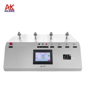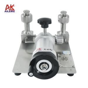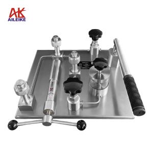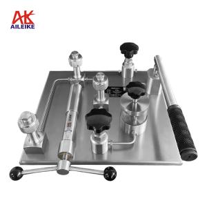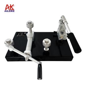


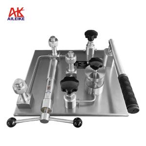
AILEIKE ALKD12A Electric Pressure Calibration Stand: Standardized Operating Procedure for Pressure Gauge Calibration, Testing, and Measurement
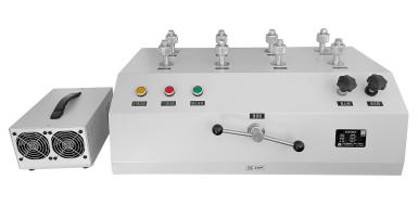
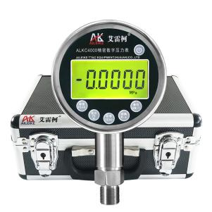
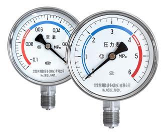
To standardize the metrological verification of pressure gauges, ensure the accuracy and reliability of pressure measurement data, and guarantee the metrological performance of industrial measurement and control instruments complies with regulations, full-range metrological performance verification was conducted on stainless steel pressure gauges. For this calibration, the AILEIKE ALKD12A electric pressure calibration bench was used as the pressure source, paired with the ALKC400D precision digital pressure gauge as the reference instrument, to perform indication measurements across the positive pressure and vacuum ranges of the Y-100BF stainless steel pressure gauge. The entire calibration process strictly adhered to metrological specifications. In a temperature- and humidity-controlled environment, point-by-point verification was performed across the full range by increasing and decreasing pressure. Key indicators, such as the instrument’s indication error, were calculated through standardized operations, stable-pressure readings, and light-tap indication recordings. The detailed operational procedures and precautions are as follows.
I. Pressure Gauge Calibration Tools
|
Name |
Electric Pressure Calibration Stand |
Precision Digital Pressure Gauge |
Stainless Steel Pressure Gauge |
|
Model |
ALKD12A |
ALKC400D |
Y-100BF |
|
Technical Specifications |
Pressure Range: -0.095 to 6 MPa Medium: Clean air Outlets: 8 Connection: M20×1.5 (F) Resolution: Pressure: min 10 Pa Current: 1 μA Power Consumption: <500 VA Power Supply: AC 220 ±10%, 50 Hz Total Weight: 35.9 kg Dimensions: 800 × 470 × 345 mm (Electric Pressure Calibration Stand) 290 × 210 × 170 mm (External Pressure Booster Pump)
|
Pressure: -0.1 to 6 MPa Accuracy: Class 0.05 Temperature Compensation: With temperature compensation Power Supply: Built-in rechargeable battery Connection: M20×1.5 (M) Net Weight: 0.6 kg Dimensions: 110×50×185 mm
|
Pressure: -0.1 to 0 MPa / 0 to 6 MPa Accuracy: Class 1.6 Material: Stainless steel Dial diameter: φ100 mm Connection: M20×1.5 (M) Net weight: 0.35 kg Product dimensions: 100 × 42 × 140 mm
|
|
Product Dimensions |
|
|
|
The entire verification process must strictly comply with current metrological technical specifications. The primary references include: JJG52-2013 “General Pressure Gauges, Pressure-Vacuum Gauges, and Vacuum Gauges with Elastic Elements,” which applies to the initial verification, periodic verification, and in-service inspections of general pressure gauges, pressure-vacuum gauges, and vacuum gauges with elastic elements, and covers on-site indicating pressure measurement instruments commonly used in industry.
II. Detailed Explanation of the Operational Process
(1) Preliminary Preparations
1. Environmental Requirements
The temperature must be maintained at (20±2) °C, with relative humidity ≤ 85% RH and no condensation. The site must be free from vibration, dust and corrosive gases.
2. Connecting the Equipment
• First, connect the external booster pump to the external pump air supply port and power supply port on the electric pressure calibration stand, and tighten the connections. Plug the calibration stand into a 220V power source and turn on the power switch.
• Connect the standard gauge ALKC400D and the pressure gauge under test (Y-100BF) to the ALKD12A outlet with a sealed connection; secure any unused outlets with plugs.
(2) Pressure Gauge Calibration Process
1. Pressurization Process
• First, open the shut-off valve, then adjust the fine-tuning pump counterclockwise to the appropriate position, and close the relief valve.
• At this point, press the air pressure increase button to build pressure up to the required value. When approaching the target pressure, release the button, then use the fine-adjustment pump to turn clockwise to the calibration value of 1 MPa. Once the pressure has stabilized and the standard gauge reading no longer fluctuates, check the pressure reading on the pressure gauge under test. Then, gently tap the side of the pressure gauge’s case with your finger (never tap the glass or strike it forcefully), observe the pointer position, and record the reading after the tap has stabilized. Use the reading after tapping as the actual calibration reading for that pressure point, and calculate the error.
• Continue pressing the air pressure boost button to increase the pressure until it reaches approximately the calibration value, then stop. Use the fine-adjustment pump to adjust the pressure to the calibration value of 2 MPa. Check the pressure reading on the pressure gauge under test, tap the pressure gauge, and record the reading after the tap has stabilized.
• Repeat the same procedure to adjust to the calibration points of 3 MPa, 4 MPa, 5 MPa, and 6 MPa. Check the pressure reading on the pressure gauge under test, tap the gauge, and record the reading once it has stabilized after the tap.
• Note: If the reading gradually drops during pressurization (indicating a slight leak), close the shut-off valve to maintain a stable pressure. Continue pressurizing using only the fine-adjustment pump.
2. Depressurization Process
• If the shut-off valve is closed, open it first before proceeding with the pressure reduction.
• First, press the pressure reduction button to reduce pressure. Stop when the pressure reaches approximately the calibration value, then use the fine-adjustment pump to adjust to the calibration value of 5 MPa. Check the pressure reading on the pressure gauge under test, tap the gauge, and record the reading once it stabilizes after tapping.
• Repeat the same procedure to adjust the pressure to the calibration values of 4 MPa, 3 MPa, 2 MPa, and 1 MPa. Check the pressure reading on the pressure gauge under test, tap the gauge, and record the reading once it has stabilized after tapping.
3. Pressure Relief Process
Open the pressure relief valve to gradually release the pressure in the pipeline. When the pressure reaches 0, the measurement is complete.
(3) Vacuum Calibration Process for Pressure Gauges
1. Pressurization Process
• First, remove the gauge under test for measuring positive pressure and install the gauge under test for measuring negative pressure. Adjust the fine-tuning pump clockwise to the appropriate position, then close the pressure relief valve.
• Press the vacuum boost button to create a vacuum; stop when the vacuum reaches approximately the calibration value, then use the fine-adjustment pump to adjust the vacuum to -0.02 MPa. Check the pressure reading on the pressure gauge under test, tap the gauge, and record the reading once it stabilizes after tapping.
• Continue using the vacuum boost button to create a vacuum until it reaches approximately the calibration value, then stop. Use the fine-tuning pump to adjust the vacuum to -0.04 MPa below the calibration value. Check the pressure reading on the pressure gauge under test, tap the gauge, and record the reading once it stabilizes after the tap.
• Repeat the same procedure to set the vacuum to the calibration points of -0.06 MPa, -0.08 MPa, and -0.095 MPa. Check the pressure reading on the pressure gauge under test, tap the gauge, and record the reading once it has stabilized after the tap.
2. Depressurization Process
• First, press the vacuum button to reduce the pressure; stop when the pressure reaches approximately the calibration value. Then, use the fine-tuning pump to adjust the vacuum to -0.08 MPa. Observe the pressure reading on the pressure gauge under test, tap the gauge, and record the reading once it has stabilized after tapping.
• Repeat the same procedure to adjust the vacuum to -0.06 MPa, -0.04 MPa, and -0.02 MPa. Check the pressure reading on the pressure gauge under test, tap the gauge, and record the reading once it has stabilized after tapping.
3. Pressure Relief Process
Open the relief valve to gradually release the pressure in the pipeline. When the pressure reaches 0, the measurement is complete.
III. Precautions
Proper Use
• When measuring positive pressure, press only the “Air Pressure” button (do not press the “Vacuum” button); when measuring negative pressure, press only the “Vacuum” button (do not press the “Air Pressure” button). Switching between pressure and vacuum must be performed under pressure-free conditions.
• During calibration, ensure that the permissible error of the standard gauge is less than that of the gauge under test to guarantee accurate and reliable results that comply with metrological standards.
• Ensure the external pressurization pump is correctly connected to the ALKD12A electric pressure calibration stand. Connect the calibration stand to a 220V power source; do not connect it incorrectly.
• Follow standard operating procedures. When pressurizing or depressurizing the ALKD12A electric pressure calibration stand, do so slowly to avoid pressure surges.
• Pressurize to the calibration point and record the reading once the standard gauge’s value has stabilized; for the pressure gauge under test, gently tap the case after the pressure has stabilized, and use the reading immediately after the tap as the final reading to ensure accuracy.
• Upon completion of the test, slowly depressurize to zero and ensure there is no residual pressure before removing the pressure gauge under test.
Maintenance and Calibration Schedule
• Perform periodic metrological verification on the ALKC400D precision digital pressure gauge (recommended once a year) to ensure measurement accuracy meets standards.
• Turn off the power when the pressure gauge is not in use; if it will be out of service for an extended period, recharge it once every three months.
• The lubricating oil in the electric pressure calibration stand should be checked and replaced every six months or after 500 hours of operation.
• Do not open the equipment cover for maintenance without the appropriate technical skills and testing equipment; adjusting or replacing components is strictly prohibited.
• If the electric pressure calibration stand will not be used for an extended period, depressurize it before storage and cover it with a cloth cover to prevent dust from entering the instrument.
IV. Conclusion
Strict adherence to these operating procedures ensures the standardized completion of full-range reading inspections and metrological performance verification for pressure gauges, enables precise calculation of reading errors at each calibration point, and guarantees that measurement results are traceable, compliant, and valid. During routine inspections, strictly follow operating procedures, correctly distinguish between positive pressure and vacuum operating modes, implement periodic verification of standard instruments, and perform routine maintenance on equipment to ensure the long-term stability and reliability of the calibration system.
Related News