

Operation procedure and metrological testing specification for calibration of AILEIKE 100MPa high-pressure switch
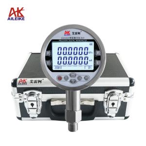
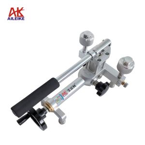
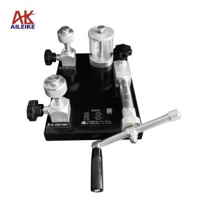
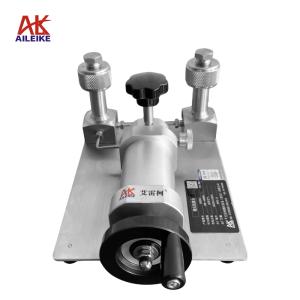
The pressure switch is a crucial control and protection component in industrial high-pressure automatic control systems. Its actuation and reset accuracy affect the operation and production stability of equipment, necessitating regular standardized calibration. This time, we used the ALKT804 hydraulic calibration bench and ALKC400A digital pressure calibrator to conduct the calibration operation, strictly adhering to temperature and humidity environmental specifications. We standardized the operations of liquid injection and exhaust, pipeline docking, and wiring. With a set pressure of 50MPa, we tested the switch under both normally open and normally closed conditions, accurately measuring the actuation and reset values. During the operation, we steadily adjusted the pressure, avoiding pressure shocks, standardized wiring, and accurately recorded the data. At the same time, we regularly verified the instruments and maintained the equipment, ensuring that the pressure switch responds sensitively, meets parameter standards, and complies with relevant industrial operation and metrology specifications.
1. Calibration tool for pressure switch
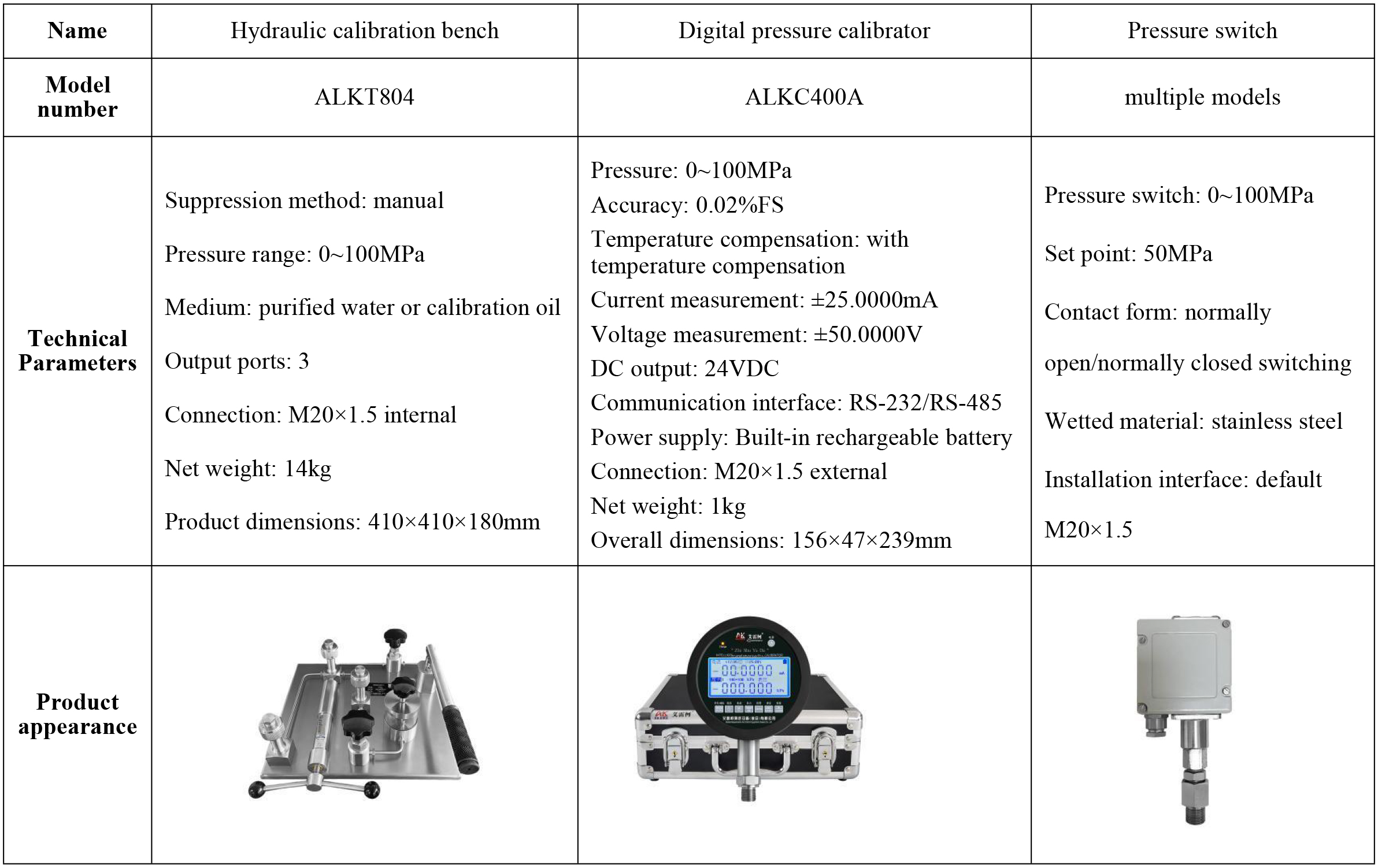
The entire verification process must strictly adhere to the current metrological technical specifications. The main references include: JJG 544-2011 "Pressure Controllers", which is applicable to the initial verification, subsequent verification, and in-service inspection of pressure, vacuum, and pressure-vacuum controllers (including mechanical and electronic types). Pressure control devices that operate without external power supply rely on pressure changes to directly drive the mechanism to achieve contact making and breaking.
II. Detailed Explanation of Operational Procedures
(I) Preparatory work
1. Environmental requirements
The temperature should be controlled at (20±2)℃, with a relative humidity of ≤85%RH, and there should be no condensation. Ensure that the site is free from vibration, dust, and corrosive gases.
2. Hydraulic platform liquid injection and pressurization for conduction
• Prepare the pressure transmission medium (pure water or calibration oil) and a syringe.
First, unscrew the pressure relief valve of the ALKT804 hydraulic calibration bench. Use a syringe to draw up the medium and inject it into the reservoir cup. Ensure that enough medium is injected (at least two-thirds of the cup). After the injection is complete, reinstall and tighten the pressure relief valve.
• Next, discharge the excess gas from the hydraulic platform. First, unscrew the plugs of the three output ports, open the pressure regulating valve, pressure relief valve, and overpressure cutoff valve, adjust the fine adjustment valve counterclockwise to the appropriate position, and close the pressure relief valve. Then, use a lever to apply pressure, allowing the pilot pressure to reach the three output ports.
3. Tool connection
• Connect the pressure switch and digital pressure calibrator ALKC400A to the output port seal of the hydraulic calibration bench ALKT804. Press the switch/peak button on the standard gauge ALKC400A to switch to the pressure switch measurement mode.
• Pressure switch preset: Open the protective cover of the adjustment knob above the pressure switch, prepare the adjustment tool, reserve a rotational adjustment range that can be turned clockwise (to increase) / counterclockwise (to decrease), and set the pressure switch setpoint.
• Wiring instructions:
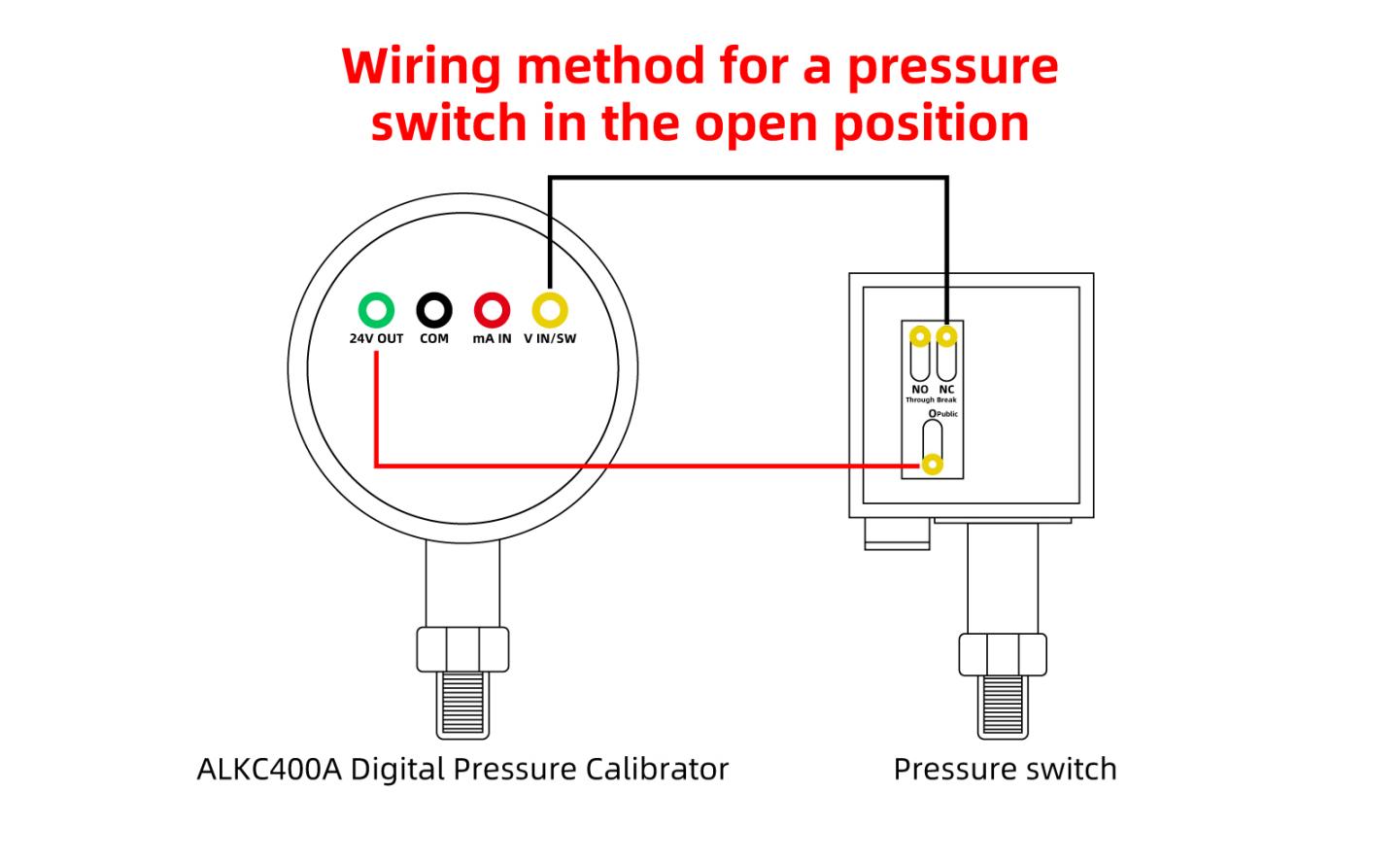
(1) Connect the ALKC400A red test pen to the 24V output interface of the standard meter, and connect the black test pen to the pressure switch measurement interface.
(2) The other end of the red alligator clip is connected to the pressure switch common terminal (COM), while the black alligator clip is connected to the normally open/break (NC) or normally closed/make (NO) terminal.
(3) Now, first clamp the black alligator clip to the normally open (NC) terminal. At this time, if the standard ALKC400A pressure switch displays the word "off", it proves that the normally open (disconnected) state of the pressure switch is normal and the wiring is correct.
(II) Operation process
Core setting steps: Set the pressure to 50 MPa according to the target, rotate the pressure switch adjustment knob slightly (clockwise for increasing pressure, counterclockwise for decreasing pressure), and cooperate with the calibration bench to apply pressure for debugging. Accurately set the pressure switch action value to the target pressure of 50 MPa, and keep the knob position fixed after the setting is completed.
1. Inspection process of closing and opening of pressure switch under normally open state
• Apply pressure using the ALKT804 lever, stopping when the pressure reaches approximately 5~10MPa. Close the pressure stabilizing valve and the overpressure cutoff valve, then use the fine adjustment to clockwise adjust to the upper cut-off value (action value) of 50MPa for the switch closure. Upon hearing the "beep" instrument buzzer prompt, the contact state transitions, and the standard gauge interface switch test changes from "off" to "on". The pressure switch switches from the disconnected state to the connected state, and the action pressure value is recorded.
• Continue to use fine adjustment to decompress counterclockwise until reaching the lower cut-off value (reset value) of 47.5 MPa when the switch is disconnected. You will still hear the "tick" sound indicating the instrument beeps, the contact state will change, and the standard gauge interface switch test will change from "on" to "off". The pressure switch will switch from a closed state to an open state, and the reset pressure value will be recorded.
• After the inspection is completed, open the pressure relief valve, pressure regulating valve, and overpressure cutoff valve in sequence. When the pressure relief reaches 0, the measurement is complete.
2. Inspection process of closing and opening of pressure switch under normally closed state
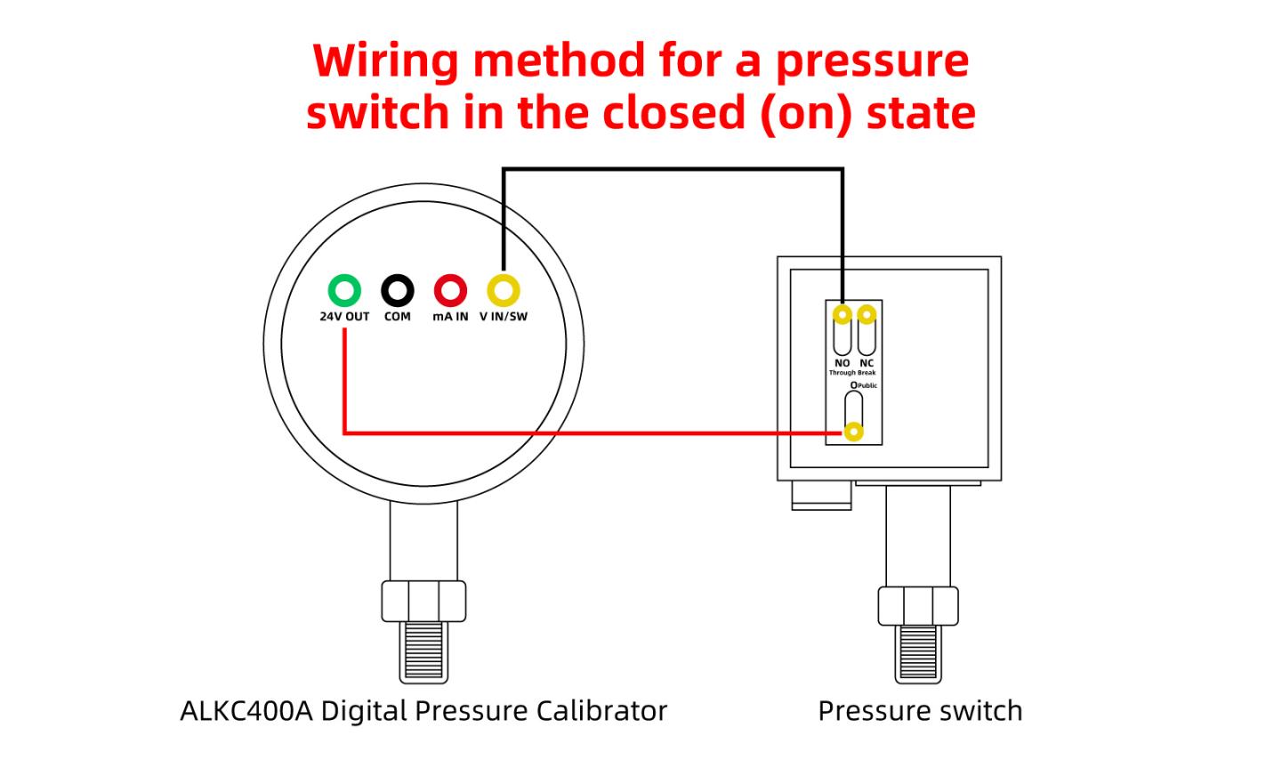
First, clip the black alligator clip onto the normally closed terminal (NO). Then, you can see that the pressure switch is in the normally closed state, and the standard ALKC400A pressure switch test displays the word "ON".
• Open the pressure regulating valve, pressure relief valve, and overpressure cutoff valve, adjust the fine adjustment valve counterclockwise to the appropriate position, and close the pressure relief valve.
• Apply pressure using a lever, stopping when the pressure reaches approximately 5~10MPa. Close the pressure regulating valve and the overpressure cutoff valve, then use fine adjustment to turn clockwise to the upper cut-off value (action value) of 50MPa where the switch is disconnected. Upon hearing the "tick" sound of the instrument buzzer prompt, the contact state will change, and the standard meter interface switch test will change from "on" to "off". The pressure switch will switch from a closed state to an open state, and the action pressure value should be recorded.
• Continue to use fine adjustment to decompress counterclockwise until reaching the lower cut-off value (reset value) of 47.5 MPa when the switch is disconnected. You will still hear the "tick" sound indicating the instrument beeps, the contact state transitions, and the standard gauge interface switch changes from "off" to "on". The pressure switch switches from the disconnected state to the closed state. Record the reset pressure value.
• After the inspection is completed, open the pressure relief valve, pressure regulating valve, and overpressure cutoff valve in order. When the pressure relief reaches 0, the measurement is complete.
III. Precautions
Standardized use
• The operation should follow standard procedures. The ALKT804 hydraulic calibration bench should be pressurized and depressurized slowly to avoid pressure shock.
• The wiring of the digital pressure calibrator ALKC400A must be clear and precise to strictly prevent reverse connections.
• The readings at the verification points should be taken after the values on the standard meter have stabilized, and the records should be kept accurate in real time.
• After the inspection is completed, slowly release the pressure to zero and ensure there is no residual pressure before removing the instrument being inspected.
Maintenance and calibration cycle
• Regularly conduct metrological verification on the ALKC400A digital pressure calibrator (it is recommended to do so once a year) to ensure that the measurement accuracy meets the standards.
• When the pressure gauge is not in use, the power should be turned off. If it is not used for a long time, it should be charged once every three months.
• If the hydraulic bench is not to be used for an extended period, it should be depressurized before storage. Pour out the liquid in the reservoir cup and cover it with a cloth to prevent dust from entering the instrument.
IV. Conclusion
This time, relying on the ALKT804 hydraulic calibration bench and ALKC400A digital pressure calibrator, we completed the standardized calibration work for pressure switches under both normally open and normally closed conditions. Throughout the entire process, we strictly adhered to specifications, smoothly adjusted pressures, and wired according to standards, avoiding pressure shock issues and ensuring the accuracy and reliability of the calibration data. Regularly conducting specialized calibrations for pressure switches can effectively identify common faults and hidden dangers such as pressure drift and contact failure. Combined with annual instrument verification and routine equipment maintenance, it can continuously ensure calibration accuracy, stabilize the working performance of pressure switches, eliminate equipment operation hazards, and provide strong support for the long-term and stable operation of industrial high-pressure systems.
Related News